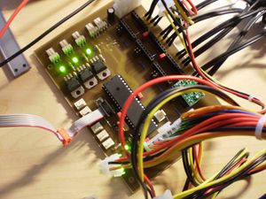
Generation 7 Electronics
Release status: working
| Description | Generation 7 Electronics
|
| License | GPL v2
|
| Author | |
| Contributors | |
| Based-on | [[]]
|
| Categories | |
| CAD Models | |
| External Link | (none)
|
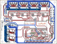
This is a complete set of electronics designed to be manufactured on RepRap machines. Replication is what makes RepRap unique, so this is extended to electronics now. All PCBs can be manufactured on your Mendel, Prusa Mendel, Huxley, or on a general CNC milling machine.
The electronic design is much like a "RAMPS with integrated Arduino". Many details were added or refined to guarantee even smoother and more comfortable operation. It started out with the Gen2OnABoard design and also took over a number of features from the various Pololu_Electronics variants.
- Discuss this set of electronics in the Generation 7 Electronics forum thread.
- Follow development and download files at the Generation 7 Electronics GitHub repository.
Contents
Design Goals
- PCB easy to manufacture on a RepRap.
- All parts on one board. Except for the Opto Endstops, of course.
- Enough components to run a Mendel or Huxley with extruder and heated bed.
- Easy to set up. For example, this would include an USB port.
- Well available and cheap parts.
- Based on the ATmega644.
- Well suited for community driven development.
Features & Specifications
- Single board solution.
- Dimensions about 100 x 130 mm.
- Single sided PCB.
- Processor: ATmega644 (Atmel Corp.)
- Pololu stepper drivers, exchangeable.
- 4x stepper motor drivers with 1/16 microstepping.
- TODO: on-board USB-RS232 converter.
- Integrated hardware for driving one extruder (stepper, heater and thermistor).
- Integrated hardware for a heated bed (heater, thermistor).
- Integrated hardware for driving a fan.
- Ready to be hooked up onto a generic PC power supply unit (PSU) via it's 20-pin connector.
- Power supply via only the 4-pin Molex connector supported as well.
- Use of standard connectors.
- Motor connector layout prepared for both, 4 mm or 200 mil spaced components. This allows Gen3 type plugs as well as screw terminals.
- Debug LEDs for power, Fan and both heater outputs.
- Can turn PSU on and off in software, when supplied via the 20-pin connector.
- Reset button.
- ICMP header.
- I2C header.
Releases
10. Feb 2011: v1.0
New features: it works. Isn't that the most important thing on an 1.0 release?
How to get it
You want three groups of parts:
PCBs
Get Gen7 Board and Gen7 Endstop PCBs from Traumflug.
As Gen7 is designed to be manufactured on a RepRap, you can make PCBs yourself, of course. How to do this on a RepRap or a general milling machine is described later on this page. You want one "Gen7Board" PCB and up to six "Endstop" PCBs. Yet another way is to purchase from one of the many houses specialized in manufacturing prototype PCBs. Gen7 is single sided, so this won't cost a fortune.
Electronic components
Get Gen7 Components Kits and Gen7 Connectors Kits from Traumflug.
If you want to assemble the collection yourself, see the #Parts Lists section.
Pololus
You need four Pololus. Only few general electronics dealers offer them, but many RepRap specific shops have them in stock.
Parts Lists
To assemble or verify these lists, open the layout with gEDA/PCB and export a "BOM". This will give you a list of all required components.
Special considerations:
- The Pololu Stepper Drivers want two single rows of 8 pin female connectors soldered into the board, so get these.
- The Stepper Drivers come with their male headers, so there's no need to purchase them seperately.
- Don't forget enough (8-9) jumpers for the jumper headers.
- Resistors with 0.25 W are on the safe side, even if the footprint name reads "0.125".
- The Pololus can be operated with up to 35 V, so you may want like-rated electrolytic capacitors.
- You may want to add the cable side of the connectors, their crimp pins and some wire.
Board
| Name | Count | Designations | Vendors | Remarks | |||
|---|---|---|---|---|---|---|---|
| Resistor 180 Ohms | 2 | R16, R18 | Reichelt | Völkner | Farnell | RS | |
| Resistor 560 Ohms | 3 | R14, R22, R23 | Reichelt | Völkner | Farnell | RS | |
| Resistor 1 kOhms | 7 | R2, R6, R8, R10, R11, R12, R13 | Reichelt | Völkner | Farnell | RS | |
| Resistor 4.7 kOhms | 2 | RT1, RT2 | Reichelt | Völkner | Farnell | RS | |
| Resistor 10 kOhms | 3 | R1, R3, R30 | Reichelt | Völkner | Farnell | RS | |
| Ceramic Capacitor 22 pF | 2 | C3, C4 | Reichelt | Völkner | Farnell | RS | |
| Ceramic Capacitor 0.1 uF | 12 | C5, C8, C9, C10, C11, C12, C13, C14, C16, C17, C18, C19 | Reichelt | Völkner | Farnell | RS | |
| Electrolytic Capacitor 10 uF | 2 | CT1, CT2 | Reichelt | Völkner | Farnell | ||
| Electrolytic Capacitor 100 uF | 3 | C1, C2, C6 | Reichelt | Völkner | Farnell | ||
| Coil 100 uH | 1 | L1 | Reichelt | Völkner | Farnell | ||
| Diode 1N4004 | 3 | D1, D2, D3 | Reichelt | Völkner | Farnell | ||
| LED 5 mm Green | 5 | LED2, LED3, LED4, LED5, LED6 | Reichelt | Völkner | Farnell | ||
| Crystal 16 MHz | 1 | U6 | Reichelt | Völkner | Farnell | ||
| Reset Switch | 1 | RESET | Reichelt | Völkner | Farnell | ||
| Socket for the ATmega | 1 | U1 | Reichelt | Völkner | Farnell | ||
| ATmega 644 (or 644P) | 1 | Reichelt | Farnell | ||||
| MOSFET IRFZ 44N | 3 | Q1, Q2, Q3 | Reichelt | Völkner | Farnell | RS | |
| 0.6 mm Wire | 50 cm | for the wire bridges of single sided PCBs | |||||
| Name | Count | Designations | Vendors | Remarks | |||
|---|---|---|---|---|---|---|---|
| Motor Header Molex 26-48-1045 (4 Pin) | 4 | X_MOT_0.156, Y_MOT_0.156, Z_MOT_0.156, E_MOT_0.156 | RS | This is the one also used in Gen2 and Gen3 Electronics | |||
| Cable Connector for the above | 4 | RS | |||||
| Crimp Contact for the above | 16 | RS | |||||
| Alternative Motor Header | 4 | X_MOT_0.156, Y_MOT_0.156, Z_MOT_0.156, E_MOT_0.156 | Völkner | working, but incompatible alternative to the Molex 26-48-1045 | |||
| Cable Connector for the above | 4 | Völkner | |||||
| Crimp Contact for the above | 16 | Völkner | |||||
| Jumper Header 2 Pin | 9 | J2, J3, J5, J6, J8, J9, J11, J12, J13 | Reichelt | Völkner | RS | cut them into appropriate pieces | |
| Jumper for the above | 9 | Reichelt | RS | ||||
| ICSP Header | 1 | CONN6 | Reichelt | RS | alternatively, assemble this out of the remainings of the Jumper 2 Pin Headers | ||
| Misc Header | 1 | MISC | Reichelt | Völkner | cut them to appropriate length | ||
| Pololu Header | 8 or 4 | U2, U3, U4, U5 | Reichelt | Völkner | cut them to appropriate length, you want 8x 8 pins | ||
| Disk Power Header | 1 | CONN2 | Reichelt | RS | |||
| ATX20 Power Connector | 1 | CONN1 | RS | ||||
| Molex KK100 3 Pin Header | 12 | HEATER1, HEATER2, FAN1, TEMP1, TEMP2, I2C, X_MIN, X_MAX, Y_MIN, Y_MAX, Z_MIN, Z_MAX | Reichelt | RS | Reichelt are tested to be fully compatible with Molex | ||
| Cable Connector for the above | 12 | Reichelt | RS | ||||
| Crimp Contact for the above | 36 | Reichelt | RS | ||||
| Molex KK100 6 Pin Header | 1 | SERIAL | RS | alternatively, use the same as for Jumper 2 Pin | |||
| Cable Header for the above | 1 | RS | |||||
| Crimp Contact for the above | 6 | RS | |||||
| Heatsink for the Pololus | 1 | Völkner | RS | ||||
| Cyanacrylate Glue | 4 drops | for glueing the heatsinks onto the Pololus | |||||
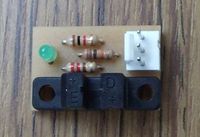
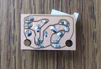
Opto Endstop
TBD
Opto Endstop Generation 2-3 Compatible
This is the same endstop as above, just with a header pin layout compatible to Generation_2_Electronics and Generation_3_Electronics. Identical parts requirements.
Miscellaneous
Generation 7 Electronics uses a TTL header for serial communications to the host. As many modern PCs lack a serial port, these need an appropriate USB to TTL cable:
| USB to TTL Cable | Mouser | Adafruit Industries | MAKE Store | MakerBot Industries |
|---|
In case your PC features a serial port or you already own an USB to Serial converter without a cable, you need an adapter cable.
| Serial Adapter Cable | TBD |
|---|
Assembly Instructions
- To find out which components to put where, have the layout on your PC screen available.
- PCBs fabricated with Voronoi paths need more heat, so raise your soldering iron's temperature by about 20 deg Celsius.
- Start with the flattest parts, usually resistors. This way, components won't fall out when you lay the PCB on it's front for soldering. Then continue with parts of raising height, connectors are usually among the last ones.
Board
- The coil 100 uH looks just like a resistor. It's a bit thicker and comes with rings brown-black-brown.
Opto Endstop
TBD
Opto Endstop Generation 2-3 Compatible
This is the same endstop as above, just with a header pin layout compatible to Generation_2_Electronics and Generation_3_Electronics.
- Take care to not overheat the photo sensor. Solder one pin on each side, then make a pause of a minute before continueing.
- As LEDs have to be inserted the right way, they have legs of different length. The longer leg (+) goes into the hole closer to the photo sensor, the shorter one (-) into the hole closer to the border.
Firmware
In principle, you can run any of the RepRap Firmwares on this board. Adjust the I/O pin layout in config.h, adjust compile time options for no secondary board/no RS485 and proceed. Just like Gen2, RAMPS or similar electronics.
User:Jacky2k wrote: I discovered a bad problem with the board wich can destroy you ISP programmer or the ATMega! When you are using the board without the 20 pin ATX connector do NOT programm the board while the endstops are plugged in! The endstops may hold some lines of the ISP low. As a workaround pull out the endstops (X_MAX, X_MIN and Y_MIN) or use the 20 pin ATX connector when programming and don't forget to remove the jumper J13 when using the ATX connector!
Configurations
You can try to use one of the following configurations for different firmware. But that may be a problem because the firmware versions are changing so fast that this wiki cannot be up to date every time, so the configuration files may become incompatible.
- Teacup master branch in conjunction with a prepared config.h. Note: "FiveD on Arduino" is the old name of Teacup Firmware.
- Original FiveD.
Pinout
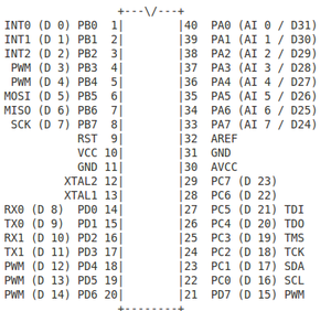
You may need the pinout for creating or porting a firmware:
| Function | ATMega Name | FiveD on Adruino | Original firmware | Direction in firmware |
|---|---|---|---|---|
| X Step | PC3 | DIO19 | 19 | Digital Output |
| X Direction | PC2 | DIO18 | 18 | Digital Output |
| X Min | PB7 | DIO7 | 7 | Digital Output |
| X Max | PB6 | DIO6 | 6 | Digital Output |
| Y Step | PC7 | DIO23 | 23 | Digital Output |
| Y Direction | PC6 | DIO22 | 22 | Digital Output |
| Y Min | PB5 | DIO5 | 5 | Digital Output |
| Y Max | PB4 | DIO4 | 4 | Digital Output |
| Z Step | PA5 | DIO26 | 26 | Digital Output |
| Z Direction | PA6 | DIO25 | 25 | Digital Output |
| Z Min | PB3 | DIO3 | 3 | Digital Output |
| Z Max | PB2 | DIO2 | 2 | Digital Output |
| Extruder Step | PA3 | DIO28 | 28 | Digital Output |
| Extruder Direction | PA4 | DIO27 | 27 | Digital Output |
| Power Enable | PD7 | DIO15 | 15 | Open Drain Output, active low |
| Motors Enable | PA7 | DIO24 | 24 | Digital Output |
| Heater 1 | PA0 | DIO31 | 31 | Digital Output |
| Heater 2 | PB0 | DIO0 | 0 | Digital Output |
| Fan 1 | PB1 | DIO1 | 1 | Digital Output |
| Temp 1 | PA1 | AIO1 | 1 | Analog Input |
| Temp 2 | PA2 | AIO2 | 2 | Analog Input |
Development
Status
24.12.2010: A first version of the Gen7 board has been etched and is beeing tested. The hardware seems to work, but the software still needs to be ported and tested with a RepRap.
29.12.2010: Some patches were made in the firmware to support endstops and homing. The patched firmware can be downloaded in the firmware section.
30.12.2010: Some more patches to the firmware. Current firmware seems to be stable and working. Not 100% tested yet.
04.01.2011: We found some bugs in the firmware again. All of them seems to be fixed, release is planned tomorrow.
05.01.2011: Uploaded current firmware with a lot of patches.
08.01.2011: Some little modifications of the PCB are required. Pull-Up resistors for I²C are missing, we want to change some headers to more common one, some resistor values are missing, ...
12.01.2011: I discovered a bad problem with the board wich can destroy you ISP programmer or the ATMega! When you are using the board without the 20 pin ATX connector do NOT programm the board while the endstops are plugged in! The endstops may hold some lines of the ISP low. As a workaround pull out the endstops (X_MAX, X_MIN and Y_MIN) or use the 20 pin ATX connector when programming and don't forget to remove the jumper J13 when using the ATX connector!
09.02.2011: The master branch of FiveD on Adruion firmware is ported and seems to work but is not tested 100%. The config file for the firmware will come soon.
History
(Well, that part of the history which didn't result in a Release).
The Forum thread (german) where everything started.
Layout, PCB Editing
Gen7 uses gEDA, a true open source set of Electronics Development Applications (EDA). While gEDA has a bit of a learning curve and has some room for improvement regarding the graphical user interface, it's reliable, fast and well suited for the task. gEDA is available for Linux and Mac OS X and has ready-to-use packages on Debian/Ubuntu and SuSe. To install it on Ubuntu, simply type
sudo apt-get install geda geda-utils geda-xgsch2pcb
and you'll find schematics and PCB layout editor applications in your applications menu.
Typical Work Loop
RepRap is all about evolution of machines and lowering entry barriers into their (self-)replication, so here you have an easy how-to type description of a typical work loop for changing these electronics with the gEDA/PCB tool chain.
Download the files with Git or GitHub's download button. In the later case choose to download source and unpack that when done.
- Always start editing with the project (.gsch2pcb suffix) file. You can open it by double-clicking it.
- Select the schematics and use the button below the list to open it.
- When done, save it and return to the project.
- Open the PCB using one of the buttons to the right. Both have almost the same functionality.
- If you have choosen to update the PCB, footprints no longer in use will have vanished and new or previously missing ones appear in the upper left corner. An updated list of connections (netlist) will have been loaded. Update the rats nest to find areas requiring work.
- When done, save it and return to the project.
You get the idea?
PCB Manufacturing
gEDA can export PCBs to the Gerber and other file formats, of course.
Milling
On how to proceed further with that, see the PCB Milling page.
Etching
For etching, you likely want to reduce the amount of etched copper to a minimum. One way to get there perfectly, is to lay a ground plane into the layout.
Note: if you're in a hurry, you can leave out the step removing the tracks on the "GND-sldr" layer and setting Thermals. It'll work anyway.
- Open the layout in PCB.
- Switch to the "GND-sldr" layer.
- Remove all tracks on this layer ( = all light blue ones = all of the GND net minus vias and bridges, find the net with Menu -> Window -> Netlist).
- Draw a RECT (find the tool in the left bar) as big as the entire board.
- Do an "optimize rats nest" (o-key).
- Some non-GND tracks might be shortened with the new ground plane. Move the mouse over each of these tracks and press the "j" key (on your keyboard). Works for tracks hidden behind the ground plane as well, you'll see the difference immediately.
- For pins and pads you actually want to connect to the ground plane, set a Thermal (THRM tool to the left).
- Loop the last two steps until you get congratulations (no errors) on "optimize rats nest".
- In case the default clearance between the copper plane and pins/tracks are not sufficient for your purposes, you can adjust them with some command line work:
- Switch to the "solder" layer.
- Select Menu -> Edit -> Select all visible.
- Select Menu -> Windows -> Command Entry.
- Type the following and hit Enter:
ChangeClearSize(selectedlines, 0.5, mm)
- Repeat the above with
selectedpinsinstead ofselectedlines. - Repeat both of the above on the "Vcc-sldr" layer.
- As you probably guessed already, you can change this "0.5" to arbitrary values and "mm" to "mil", and use different values for each of the 4 groups.
- You're done.
On how to proceed with this etching-optimized board, see ... [Links needed]
Bug fixing, Sending Changes
This is community development, so getting changes from everyone is more than welcome. Write them to the forum, to the reprap-dev mailing list, use GitHub's Issue Tracker, whatever is most convenient for you. If you fork the repository at GitHub, you can also send Traumflug pull requests.
