Hall-Θ/nl
|
English • العربية • български • català • čeština • Deutsch • Ελληνικά • español • فارسی • français • hrvatski • magyar • italiano • română • 日本語 • 한국어 • lietuvių • Nederlands • norsk • polski • português • русский • Türkçe • українська • 中文(中国大陆) • 中文(台灣) • עברית • azərbaycanca • |
Release status: working
| Description | Hall effect endstop sensor
|
| License | Attribution - ShareAlike
|
| Author | |
| Contributors | |
| Based-on | [[]]
|
| Categories | |
| CAD Models | see files
|
| External Link |
Contents
Beschrijving
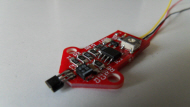
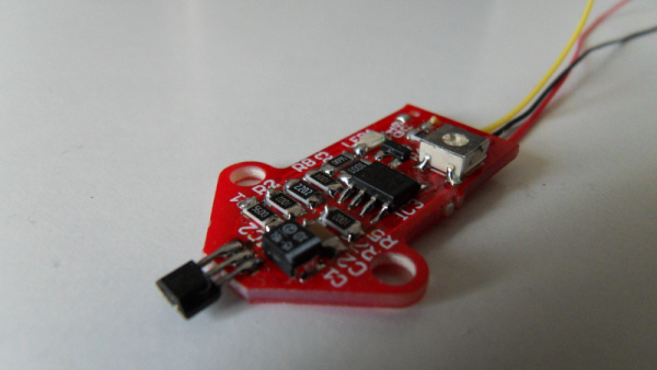
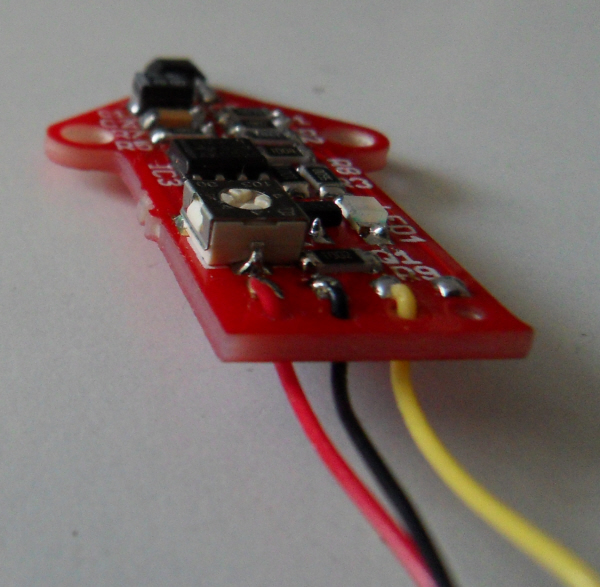
De Hall-O is een Hall Effect Sensor 'Printed Cuircuit Board' (PCB) welke reageert op magnetische krachten.
Het is een contactloze nabijheid sensor, 32 mm lang, welke de afstand precies meet tot een magneet.
Deze sensor is zeer geschikt als precieze eindstop .
De sensor wordt gevoed met 5V gelijkstroom (DC = Direct Current), en geeft twee meetsignalen: analoog en digitaal.
Waneer het magnetische veld sterker wordt, zal het uitgangssignaal langs een lineaire schaal of naar Vmax of naar GND (zuid of noordpool van de magneet) bereiken .
Met een magneet van 3mm in diameter en een dikte van 2mm (3x2 mm), zal de sensor op ongeveer een afstand van 4 mm gaan meten en zijn maximale waarde Vmax bereiken op ongeveer een afstand van 1,5 mm.
Voor de laatste stand van zaken volg mij op blog
Prijs voor een complete Hall-O sensor is € 9,- (gesoldeerd, incl. 1m kabel en magneet)
Prijs voor een Hall-O zelfbouw kit € 7,- (incl. 1m kabel en magneet)
Prijs voor de print Hall-O € 3,50
Voor aankopen of meer informatie, kun je kijken op MaukCC, of contact opnemen met een van de distributeurs.
Alle ontwerpen worden gelicenseerd onder Attribution - ShareAlike.
Analog output
The analog output comes straight from the sensor and is (when no magnetic force is applied) 2,5V.
When the south pole of a magnet approaches the sensor, the voltage will go up to Vcc.
When the north pole of a magnet approaches the sensor, the voltage will go down to GND.
If the Hall-O is used as an endstop device, 1 unit can be used for min and max endstop.
This can be done by applying a north pole to one side, and a south pole to the other.
Digital output
Digital output only works with south pole magnetics.
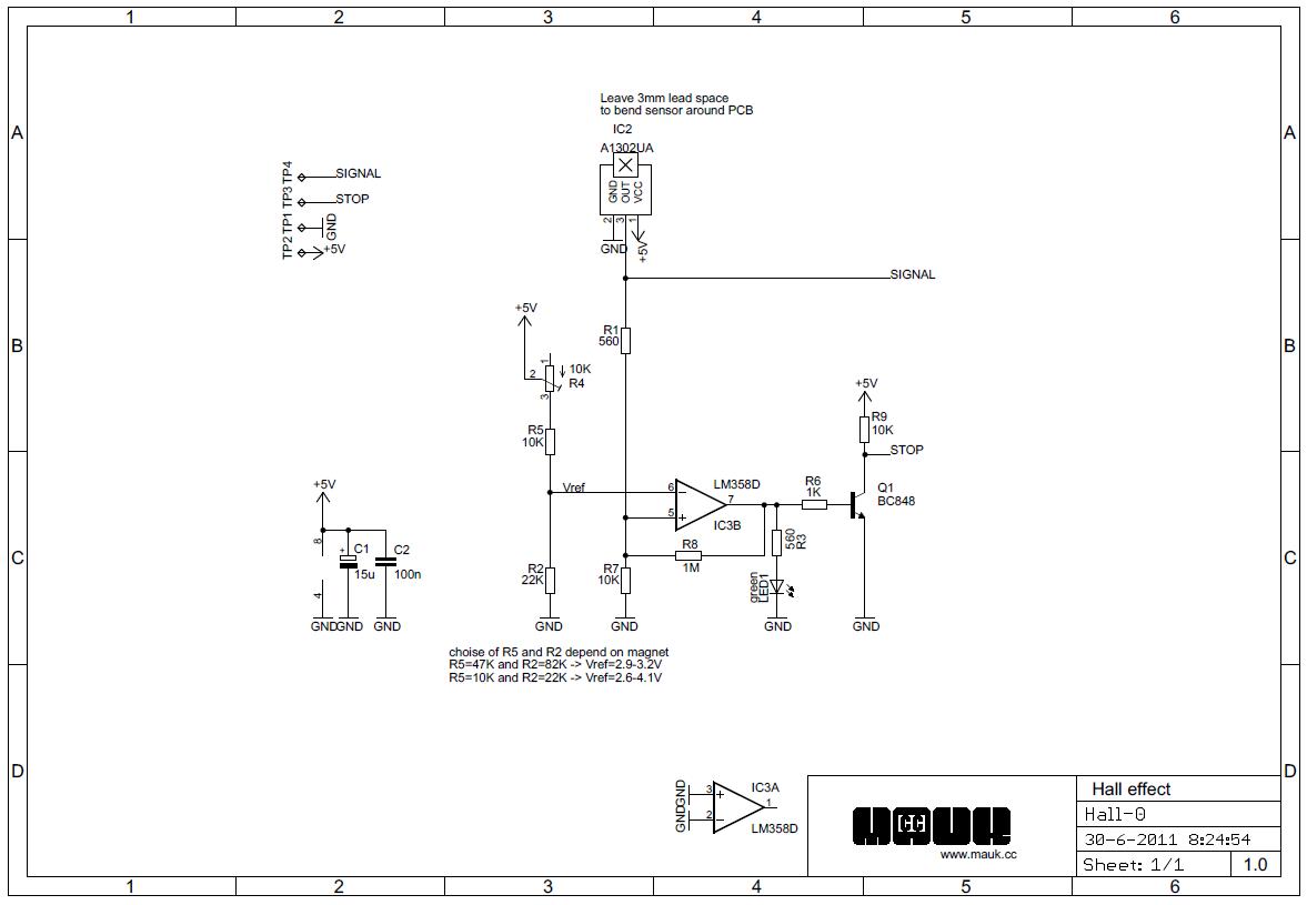
When the output voltage becomes greater than the Vref, the Digital output will go from 5V to GND.
Vref is regulated by a potentiometer.
Normally R2=22K and R5=10K, and Vref will give a range from 1 to 6 mm of the hall sensor.
When R2=82K and R5=47K, Vref will give a range from 3 to 4 mm of the hall sensor. So 1 turn of the potentiometer will have a higher resolution
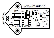
Printplaat afbeelding en schema
Files
The holders for mendel and Cartesio are found at Thingiverse
Onderdelen Lijst
| Qnty | PartNr | device | Vendor | |
| 1 | LED1 | LED Green 1206 | ||
| 2 | R1, R3 | 560 R1206 | ||
| 3 | R5, R7, R9 | 10K R1206 | ||
| 1 | R8 | 1M R1206 | ||
| 1 | R2 | 22K R1206 | ||
| 1 | R6 | 1K R1206 | ||
| 1 | R4 | 10K TRIMM3314 | ||
| 1 | Q1 | BC848 | ||
| 1 | IC2 | A1302UA | ||
| 1 | C1 | 10uF/16V tant caseA | ||
| 1 | C2 | 100nF | ||
| 1 | IC3 | LM358D | ||
| 1 | Magnet 3x2 | |||
| 1m | Cable | |||
| 1 | Hall-Θ PCB | MaukCC |
For everyone who can not get the A1302UA (RS no. 680-7504), The SS495B should be a direct replacement, but I have not tested this.
Hall-O Zelbouw kit
Er is een handleiding voor degenen die de moed hebben zelf hun Hall sensor te solderen.
De beschrijving vindt je op de Hall-O DIY kit pagina.
Setup
There is a small magnet in the bag, so be careful when you open it.
First attach the cables to the board.
Cut off 1 mm of insulation and put tin on the wire
Then push the wire through the hole at the pad, from the bottom to the top, and solder it to the pad.
Pushing it through the hole, makes sure the cables do not break from the pad when the cables move/vibrate.
Cut the cable to the desired length.
Solder the connector that comes with your "motherboard" to the cable coming from the Hall-O.
Download the Hall-O holder of choice at Thingiverse
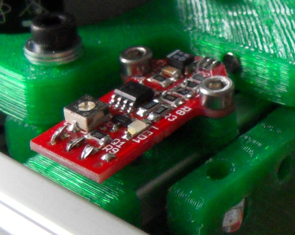
Mount the holder to the Hall-O (The distance between the mounting holes is 17mm) and to the machines frame with M3(or M4 for Cartesio) bolts.
You probably want the sensor at a 90 degree angle from the board, since this is where you are going to measure.
Mount it at about 3mm distance from the place where you actually want the Axis to stop.
The sensor should be at 3mm distance from a plastic printed part.
Now to get to the interesting part: mounting the supplied magnet.
Make a mark on the plastic printed part nearest to the sensor.
Drill a hole of 3mm 2mm deep.
Make the hole a bit soft by holding a (hot) soldering iron to it, and push the magnet into the hole.
Do NOT hold the hot soldering iron to the magnet, or you will be left with a round metal piece.(which is a dead magnet)
You can also just use some glue to attach the magnet.
For digital application make sure the south-pole* is facing outward, otherwise the whole thing will do nothing and you have to take the magnet out again, which is a pain, I can tell you.
- You can test which side is south-pole by holding the magnet to the Hall-O sensor, 1 side of the magnet will engage the LED, and 1 side will not.(The Hall-O must be powered)
Connect the connector to the "motherboard".
Make sure in the firmware the endstop is set to invert, because it switches from 5V to GND.
It is not required to have pullup resistors enabled in your firmware, because they are on the board it self.
If it is already enabled, leave it, it will not interfere.
For digital application you can now fine tune where the axis should stop by turning the potentiometer on the Hall-Θ.
Sanguinololu
If your motherboard is the Sanguinololu, make sure the endstop link on the bottom is soldered.
