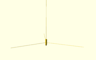
Hangprinter
Release status: Idea stage/Experimental
| Description | A RepRap using walls and ceiling as its frame
|
| License | |
| Author | |
| Contributors | |
| Based-on | |
| Categories | |
| CAD Models | OpenSCAD
|
| External Link |
Contents
Ideas the design is meant to implement
- A print-head that hangs down in a string from the ceiling.
- Put all the hardware (except AC/DC-converter) in one single unit.
It should be possible to install in a house by simply by attaching strings to anchor points in walls and ceiling, power wire to circuit board and filament to extruder.
Assumed difficulties
- Special geometry-compensating firmware
- Keeping strings tight
- Keeping rotation at zero
- Finding a reasonable home position
- Convincing people to put anchor points (screws) in walls...
Assumed advantages From Using House as Frame
- Low part count
- Easy to print, assemble, install and distribute
- Huge build volume (especially height).
- When printer is idle, one could retract all the strings. Hanging it in the z-achor point (the ceiling) with no dangeling strings might be elegant storage solution. Could make it popular in big cities, where indoor area is scarce.
Keeping strings tight
We need to know if springs are wanted/needed. Some work on this has been done
Keeping rotation at Zero
Things that will produce forces
- Dragging filament around
- Dragging power cable around
- Accelerating motors
Rotation around z-axis might be considered less harmfull since one could place the hotend in the rotational midpoint. All motors probably need to be downshifted heavily, and accelerations kept minimal. It might have to be a very slow printer. Will it help to keep all motor shafts in paralell with the z-direction in order to avoid induced xy-torque? Will it need a very thought out extruder?
Finding Home Position
Suggested procedure:
All wires have a markers that can be recognized with optical sensors at their max-length. The optical sensors are situated near the motors. Max-lengt and home-length of each wire are set in firmware.
- All motors release wire until max length markers are found.
- All motors roll in wire until home length is reached. Mechanism that keeps wires tight near motor shaft is needed for this.
