Heated Bed Theory
Release status: experimental

| Description | theory on heated beds
|
| License | unknown
|
| Author | |
| Contributors | |
| Based-on | [[]]
|
| Categories | |
| CAD Models | |
| External Link |
From time to time there's a lot of talking about the optimum heated bed. So far, a few solutions surfaced, from using industry parts to high-tech carbon fibre products. This page tries to enlighten a few of the attempts with theoretical background in the hope we get something open source and replicatable some day.
There's also the Heated Bed page, where the viewing angle is a bit more from the practical side.
Contents
Heating with an industry application
Here we have an existing solution already, the Heated WolfBed.
Warping
So far, there is no real countermeasure against warping, other than to apply this to a fairly thick sheet of aluminium, which is expected to warm up evenly, and thus to prevent warp. This is said to work reasonably, but to result in a rarther heavy bed, which in turn limits movement speeds.
Etched or Isolation Milled Copper Clad
With this approach, copper clad is manufactured in a way resulting in one (or few) tracks over the whole surface. As a voltage is applied and the resistance of the long copper track is not neglibile, the copper gets heated.
Calculation of the track length
First of all, we have to decide on an appropriate power output and use it to find out what resistance we need. 120 watts is a reasonable output for a heated bed. The resistance required to produce this power will depend on the supply voltage. For a common 12 V supply, 1.2 ohms is required:
- <math>R = \frac {V^2} {P} = \frac {(12\,V)^2} {120\,W} = 1.2\, \Omega</math>
If you fill a board with parallel track parts, connected zig-zag at the ends, the length of the entire track is approximately
- <math>l_{tr} = l_b \cdot n_{tr}</math>
where
- <math>\begin{align}
l_b & = \mbox {the length of the board} \\ n_{tr} & = \mbox {the number of parallel track parts} \end{align}</math>
<math>n_{tr}</math> can be calculated as well:
- <math>n_{tr} = \frac {w_b} {w_{tr}+w_i}</math>
where
- <math>\begin{align}
w_b & = \mbox {the width of the board} \\ w_{tr} & = \mbox {the width of one track part} \\ w_i & = \mbox {the isolation width between two track parts} \\ \end{align}</math>
The next step is to calculate the resistance of the total track. However, this is already described on the Conductive Materials page, so let's skip that here. Inserting the above two formulas into the stuff there, mixing and shaking the result a bit, solving the quadratic equitation, dropping the impossible solution, we get this:
- <math>w_{tr} = \frac {-w_i + \sqrt {w_i^2 + 4 \cdot \frac {R_{s,cu} \cdot l_b \cdot w_b} {R \cdot t_{cu}}}} {2}</math>
where
- <math>\begin{align}
R_{s,cu} & = \mbox {specific resistance of copper} \\ t_{cu} & = \mbox {thickness of the copper} \end{align}</math>
Let's insert a typical application with:
- <math>\begin{align}
R & = 1.2\, \Omega \\ R_{s,cu} & = 1.68 \cdot 10^{-2}\,\Omega \cdot mm^2 / m = 1.68 \cdot 10^{-5}\,\Omega \cdot mm \\ t_{cu} & = 35\,\mu m = 0.035\,mm \\ l_b & = 130\,mm \\ w_b & = 100\,mm \\ w_i & = 0.5\,mm \end{align}</math>
So we get:
- <math>\begin{align}
w_{tr} & = \frac {-0.5\,mm + \sqrt {0.5^2\,mm^2 + 4 \cdot \frac {1.68 \cdot 10^{-5}\,\Omega \cdot mm \cdot 130\,mm \cdot 100\,mm} {1.2\, \Omega \cdot 0.035\,mm}}} {2} \\ & = 2.044\,mm \end{align}</math>
The number of tracks is
- <math>n_{tr} = \frac {100} {2.044 + 0.5} = 39.3</math>
which needs to be rounded down to 39 for obvious technical reasons. Inserting that into the Conductive Materials formula, we get a specific resistance of 0.2348 Ω/m, or a total resistance of 39 * 0.13 m * 0.2348 Ω/m = 1.19 Ω
Experimental Results
This board is 130 mm x 50 mm and was designed to have 1500 W/m2 at 2.5 volts, or 19.5 watts. According to the above formulas it has 20 tracks, 2 mm wide:

As expected, it measures about 0.6 ohms. So, the math given appears to be approximately right.
Warping
The idea is to manufacture two such clads with tracks and to glue them together on their backs. This way both sides are heated evenly and no warp should occur.
Test Without Warp Compensation
But first, let's have a look what's going on without trying to compensate warp. The above mini bed is made from hardpaper/Pertinax/FR2 without any stiffening glass fibres inside, so a lot of warp is expected.

This is the setup. The nuts are just a weight, the screwdriver lays there to make the camera's autofocus work. The applied voltage is 5 volts, double of the designed 2.5 volts. Measurements were taken from the photo in the Gimp, at a resolution of a bit better than 0.05 mm. You have to trust me a bit on that, or I'd have to upload the whole 6x 6 MB photo files.
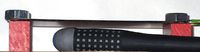
The initial measurement photo. The warp is 0.42 mm downwards.
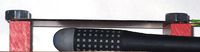
After applying voltage for one minute. The bed is straight within measuring tolerance.

After 5 minutes. Warped 0.3 mm upwards.
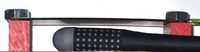
After 30 minutes. Warped 0.8 mm upwards.
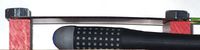
After 1 hour. Warped 0.95 mm upwards.

After cooling down. Still warped 0.3 mm upwards.


Oh yes, which heat did this setup actually reach? I must admit I don't have an appropriate thermometer. So I put a drop of water onto the plate to get an idea. In this drop tiny bubbles developed, so I guess the temperature reached is close to 100 deg celsius.
Result: It warped, as expected. This is a material which bends easily and if we get this material to not warp, we've won.
References
Embedded Carbon Fibres
Carbon fibres have two properties which make them look pretty ideal:
- Carbon fibres can conduct electricity. So, no copper or other conductor needs to be applied.
- Carbon fibres have a very small and even slightly negative temperature coefficient. Unlike most materials, carbon fibres get shorter when heated up. In combination with other materials, like glass fibres, you can achieve a zero shrink material.
The later of the two obviously requires a careful design. Throwing a bunch of fibres into a bag and filling up with resin won't suffice :-)
Warping
As there is no shrink or grow when raising temperature, there is no warp. This has been proven in many applications.
References
R&G Wiki about heatable molds and a thesis founding that.
Printed Heated Bed
Making a RepRap print it's very own heated bed? Sounds ridiculous. It might work, however:
- The bed's temperature is always below the plastic's melting temperature, so e.g. ABS might be a suitable material to manufacture a bed for printing ABS.
- Making a machine printing it's own bed means the bed is always perfectly aligned to the machine's mechanics.
A possible workflow:
- Mount a light platform where ABS sticks really well.
- Print a thin layer, as big as possible, onto this platform. This layer should leave out a groove in a zig-zag way.
- Fill this groove with a graphite slurry. This will be the electricity conducting heating element.
- Let the thing dry, then grind off artefacts from the surface.
- Connect the ends of the graphite track to the power source.
- Cover the top surface with your favourite printing tape. Kapton or whatever.
- Print.