Heated Piezo for Jetting Wax
Release status: experimental
[[image:|center|190px]]
| Description | A Piezo design that can be heated for jetting wax.
|
| License | GPL
|
| Author | |
| Contributors | |
| Based-on | |
| Categories | |
| CAD Models | |
| External Link |
Introduction
This is an piezo head that is completely makable in a RepRap machine. It was inspired by Johnrpm's Scratchbuilt_Piezo_Printhead. It is experimental, so it's reliability is not yet perfect... But it does work.
I need to do more work on the driver electronics. Then I'll see if I can add heater elements so we can inkjet waxes and wood's metal...
| no. off | part | picture key | |||||
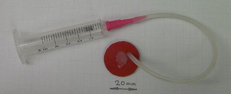
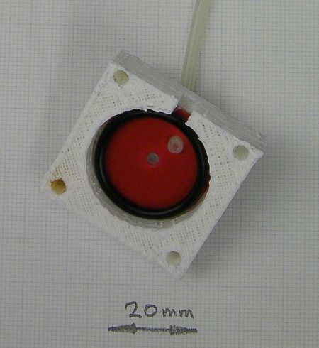
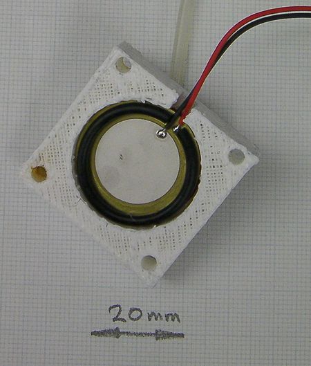
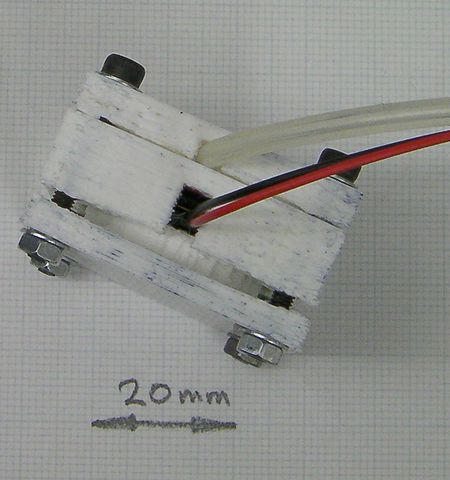
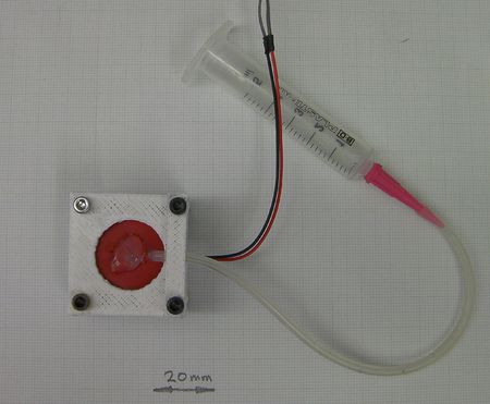
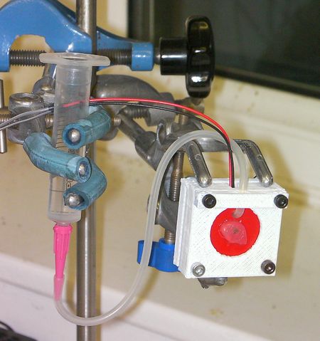
Ink supplyConnect up whatever you are using as a tank to the silicone tube. Put a little silicone grease on the other end of the tube and force it through the offset hole in the disc. It leads through from the nozzle hole side. That is to say: the tube leads out in the same direction that the finished inkjet will eject ink. Make the tube project about 1 mm through the plastic disc. Final assemblyPut the what is now the nozzle disk with the tube into the reprapped body. Have the tube next to the notch. Lightly cover one O ring with silicone grease and put it in after the disc. Put the piezoelectric buzzer in with its active face towards you in the picture. Lead its wires out through the notch. Use the scalpel to cut a short (about 2mm) section out of the second O ring. This will accommodate the wires. Put the cut O ring onto the piezoelectric buzzer. Put two washers on the 25 mm cap screws and put them through the tube clamp. Use this clamp to bend the tube through a right angle and lead it out parallel to the wires. Put the buzzer clamp on the back of the second O ring. It has a raised annular cylinder to push down on that ring. Use the two 20 mm screws to attach the other end of the device together. Tighten the screws diagonally, just a turn at a time. You want the pressure to be uniform and the clamp not to be at an angle to the body. Here is a picture of the finished device. ElectronicsCAUTION While experimenting, your hands will get wet with whatever you use for ink. Do try not to electrocute yourself... This section is temporary. I'm going to do a proper driver design with a To get it working I used a MOSFET driven by an Arduino switching 12 volts into the 24 volt secondary of a small 220 volt to 24 volt mains transformer. I put a reverse-biased diode across the transformer to dump back EMF. I connected the transformer primary (i.e. the mains side) to the buzzer. I drove it with a square wave with a mark time of 800 microseconds and a space time of 1200 microseconds. I put a push button between pin 3 on the Arduino and ground to turn the pulse train on and off. Pin 2 drives the MOSFET. Here is what is going into, and coming out of, the transformer. The top yellow trace is the output from Pin 2 of the Arduino. The bottom purple trace is the voltage across the piezo (50v/division). The transformer, being a very large inductive load, and the buzzer, being a mostly capacitive load, makes a complete mess the waveform - not much use for fine control.
Getting it workingI used tap water with a little detergent dissolved in it to reduce surface tension. Bubbles are your enemy. If there is any air in the ink cavity the device won't eject liquid. Set things up so you can easily vary the head between the ink tank and the inkjet head. When the device is working you want the head only to be about 10 mm or so. But when you are setting it up you may need a greater head to force the liquid through. With the nozzle pointing upwards, twist the device about and tap it to get all bubbles of air out of the nozzle. When you press the button on the switch attached to the Arduino you should hear the buzzer buzz, and you should see a fine jet of liquid come out of the nozzle. Remember that the piezo has a polarity: you want the short mark to eject the droplet and the longer space to allow refill from the tank. You may have to swap the leads to make things work.
|
