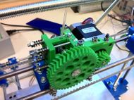
Herringbone Extruder Driver
Release status: Experimental
| Description | Herringbone Geared Nema 17 Extruder Driver
|
| License | GPL
|
| Author | |
| Contributors | |
| Based-on | |
| Categories | |
| CAD Models | |
| External Link |
| FILE ID# | TYPE | DESCRIPTION | AVAILABLE FORMATS | CREATED/RESERVED BY |
|---|---|---|---|---|
| Your-File-Name | SOLID MODEL ASSEMBLY | These are CAD files for the Solid Model Assembly | .xml.zip, .stl.zip | --Example User 12:00, Today's Date 20xx (UTC) |
| Your-File-Name | CAD FILES FOR PARTS | These are CAD files for each part. | .xml.zip, .stl.zip | --Example User 12:00, Today's Date 20xx (UTC) |
| Your-File-Name | EVEN MORE FILES | These are are even more files. | .xml.zip, .stl.zip | --Example User 12:00, Today's Date 20xx (UTC)|- |
| Your-File-Name | SOLID MODEL ASSEMBLY | This is the final finished machine | N/A | --Example User 12:00, Tomorrow's Date, 20xx (UTC) |
Please edit this and click the links to put in your own files! --Sebastien Bailard 08:34, 10 September 2010 (UTC)
This is an attempt to combine various aspects of Adrian's and Wade's extruder drivers. Specifically, It keeps Adrians extruder clamping system, uses a prime number of teeth for good wear characteristics but uses Wade's hobbed bolt to do the driving.
As the name suggests, the design uses Herringbone gears. This ensures that backlash is substantially reduced, which should result in the extruder requiring slightly less reverse, but more importantly run quieter. The design of the drive gear is somewhat experimental. As with other gears, this uses a grub screw to secure the gear to the motor shaft. However, on this design the hole goes through the root of one of the teeth. This takes up less space, and also lets you adjust the position of the gear without taking the motor off. However, whilst I've printed it fine on a commercial printer, it *may* be too intricate to RepRap. But the fix is fairly trivial.
Manufacture of the bolt is the same as Wades, but you'll need an M8x70 instead. I find it best to assemble the whole extruder, before marking where the hobbing needs to go on the bolt. A stack up of tolerances during build and assembly will probably mean that if we measure it off the CAD model it'll be wrong, or atleast not optimal..
Also, on my pictures you'll notice the layout of the bolt goes - Gear, 2X Washers, Spacer, Washer, Bearing, Washer, Gap, Washer, Bearing, Washer, 2X m8 Nuts.
You should really put 3 washers at the beginning instead of 2, (I screwed up the hobbing of the bolt). Equally, the final two nuts do not need to be done up tightly, doing so would mean the bearings become a little rough. The herringbone gears should keep everything aligned by themselves and the bolt takes all the torque, so the nuts only need to be lightly tightened.
When assembling this extruder, it is somewhat critical the gears are perfectly aligned. Herringbone gears try to self-center, if the alignment is incorrect they'll probably get damaged. I find the best way is to assemble everything, not tightening the grub screw on the drive gear, give the whole thing a couple of turns during which the gears should align, and then tighten the grub.
