LaserCut Mendel Assembly
These assembly instructions are incomplete and have been posted by a customer rather than anyone associated with the sale of LaserCut Mendels. You may also wish to refer to the LaserCut Mendel Assembly Blog which shows some assembly pictures from another customer (in that case, only the laser cut parts are from techzone).
Contents
Extruder
X Axis
X Carriage
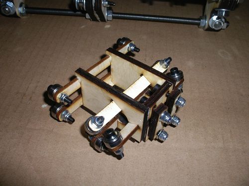
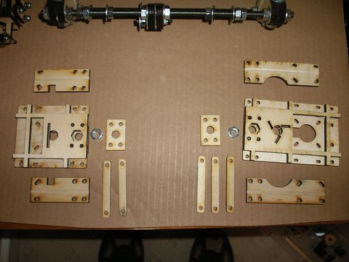 My supplied X belt was barely long enough. I installed the axis ends so that the smooth rods were almost touching the bearings. I still had to cut the belt and just clamp the ends on the x carriage to make it long enough to go round the x axis assembly.
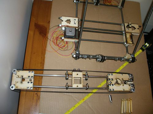
Y Axis
Y Idler
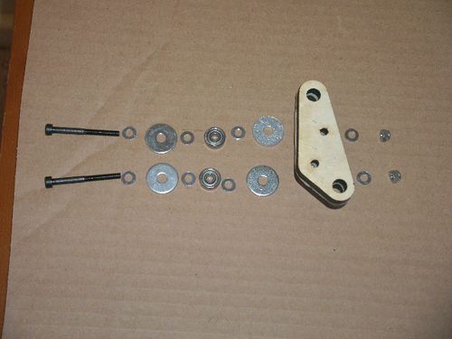
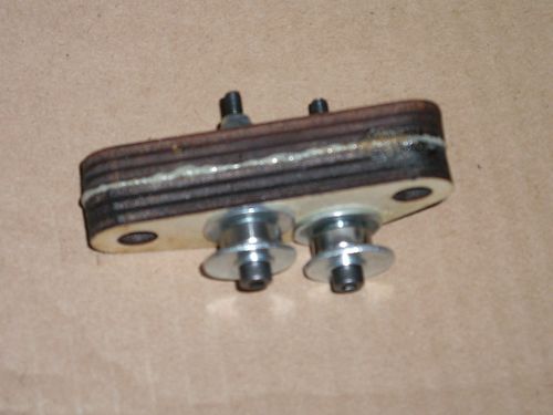
Be warned that you probably need an additional washer against each bearing to allow the belt enough space for smooth running between the mudguard washers.
Y Motor
Be warned that you probably need an additional washer against each bearing to allow the belt enough space for smooth running between the mudguard washers.
Z Axis
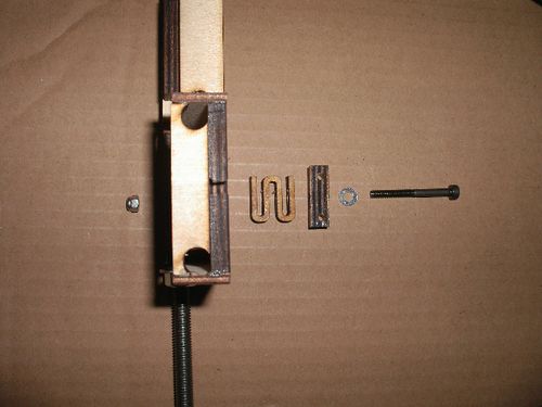
Z Leadscrew Base (one with opto)
You will need 2 of these assemblies, only one of them has the opto mount.
| Name | Qty /w opto | Qty /wo opto | Type |
| Z Leadscrew Base | 1 | 1 | Laser Cut Part |
| Opto Spring | 1 | 0 | Laser Cut Part |
| Opto Holder | 1 | 0 | Laser Cut Part |
| Bearing | 2 | 2 | Hardware |
| M4x40 | 3 | 2 | Fastener |
| M4 Washer | 9 | 8 | Fastener |
| M4 Mudguard Washer | 4 | 4 | Fastener |
| M4 Nut | 3 | 2 | Fastener |
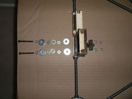
 Be warned that you probably need an additional washer against each bearing to allow the belt enough space for smooth running between the mudguard washers.
Z Motor
Z Tensioner
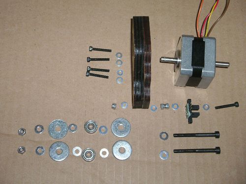
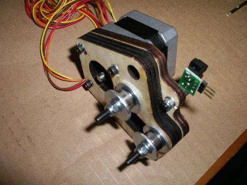
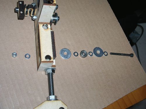
Be warned that you probably need an additional washer against each bearing to allow the belt enough space for smooth running between the mudguard washers.
Frame
Frame Sides
Left Side
BOM
| Name | Qty/assembly | Type |
| M8 Nut | 14 | Fastener |
| M8 Washer | 14 | Fastener |
| 370mm M8 Threaded Rod | 3 | Hardware |
| corner vertex | 3 | Laser Cut Part |
| Z Leadscrew base | 1 | Laser Cut Part |
| Z Motor Bracket | 1 | Laser Cut Part |
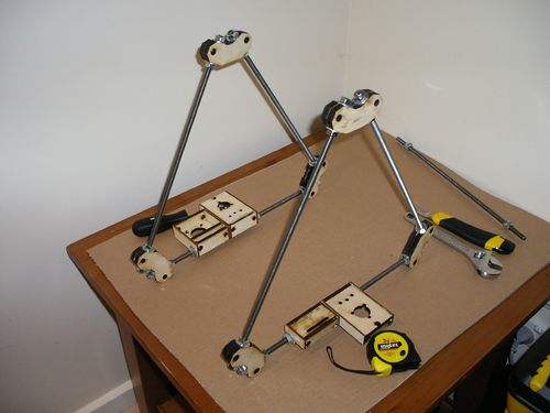
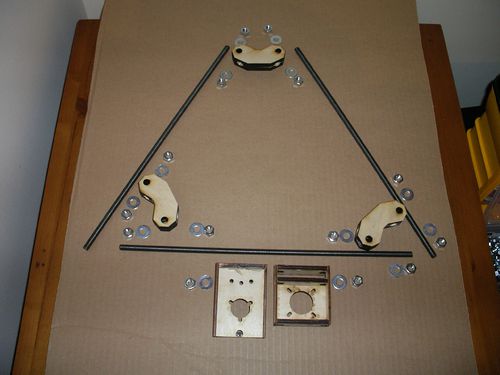
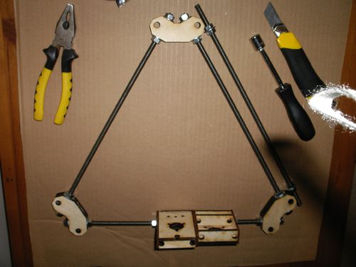
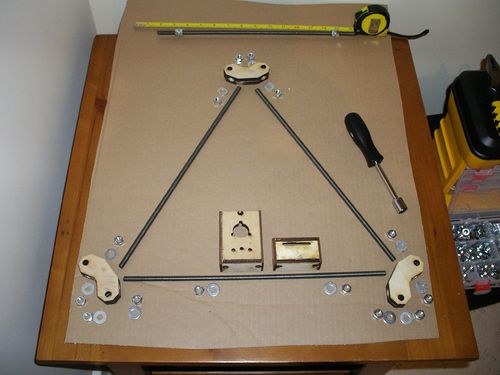
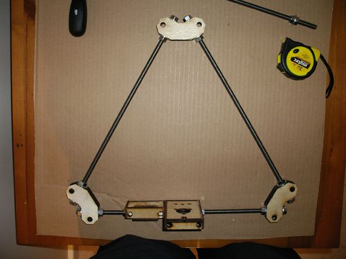
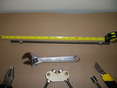
You will also need a measurement jig to get the distance between the corner vertices the same. I created a jig using one of the other bits if M8 rod, 4 nuts and 2 washers. I assembled the jig so that the outside of the two washers was 290mm apart. Then used it when tightening the nuts on the vertex pieces to ensure the spacing was right.
Right Side
BOM
| Name | Qty/assembly | Type |
| M8 Nut | 14 | Fastener |
| M8 Washer | 14 | Fastener |
| 370mm M8 Threaded Rod | 3 | Hardware |
| corner vertex | 3 | Laser Cut Part |
| Z Leadscrew base | 1 | Laser Cut Part |
| Z Tensioner Bracket | 1 | Laser Cut Part |
