Mechanical Rigidity
Mechanical Rigidity
This page goes into the basics, with illustrations, on how to ensure that a design is mechanically rigid, and also what to look for if buying an existing 3D printer. The key elements are:
- Rigidity must be achieved in all six degrees of freedom: Rotation about each of X, Y and Z, and Movement in X, Y and Z.
- The simplest rigid open structure is a triangle.
- Solid materials (plates, bars, extrusions, rods etc.) have rigidity that is proportional to their thickness (or length)
- A "lever" effect on the way that the frame is connected together is critical to take into account.
Thus, a quick guide to analysing an existing design is:
- If it is a cube design, is there support in all six faces of some kind? Either plates (polycarbonate, acrylic, plywood or hardboard at least 2.5mm thick) filling each face, or aluminium plate of sufficent thickness (minimum of 3mm depending on printer size), diagonal struts creating complete triangles, or even suitably strong and high-tension wires (again creating complete triangles to all vertices)
- If it is a Mendel style design, these are not rigid at all in their base, and rely completely on being on a flat surface, with gravity assisting to keep them down.
- If it is an "open design" without triangles (or plates), is the frame of sufficient thickness for the size (3020 for a 200x200 printer, to 8020 extrusion for a 300x300 or greater) and are the frame struts sufficiently strongly connected together?
Examples
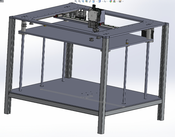
Here is a design where some advice was asked here http://forums.reprap.org/read.php?177,722199:
