Mechanical Rigidity
Mechanical Rigidity
This page goes into the basics, with illustrations, on how to ensure that a design is mechanically rigid, and also what to look for if buying an existing 3D printer. The key elements are:
- Rigidity must be achieved in all six degrees of freedom: Rotation about each of X, Y and Z, and Movement in X, Y and Z.
- The simplest rigid open structure is a triangle.
- Solid materials (plates, bars, extrusions, rods etc.) have rigidity that is proportional to their thickness (or length)
- A "lever" effect on the way that the frame is connected together is critical to take into account.
Thus, a quick guide to analysing an existing design is:
- If it is a cube design, is there support in all six faces of some kind? Either plates (polycarbonate, acrylic, plywood or hardboard at least 2.5mm thick) filling each face, or aluminium plate of sufficent thickness (minimum of 3mm depending on printer size), diagonal struts creating complete triangles, or even suitably strong and high-tension wires (again creating complete triangles to all vertices)
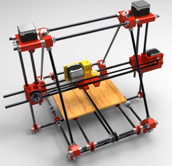
- If it is a Mendel style design, these are not rigid at all in their base, and rely completely on being on a flat surface, with gravity assisting to keep them down.
- If it is an "open design" without triangles (or plates), is the frame of sufficient thickness for the size (3020 for a 200x200 printer, to 8020 extrusion for a 300x300 or greater) and are the frame struts sufficiently strongly connected together?
Frame Examples
Mendel (Early Prusa) inadequate design
The very early Mendels (some of which are still copied and sold, particularly in China) are classic examples of significantly non-rigid design. Here is a photo:
Cube design needing improvement
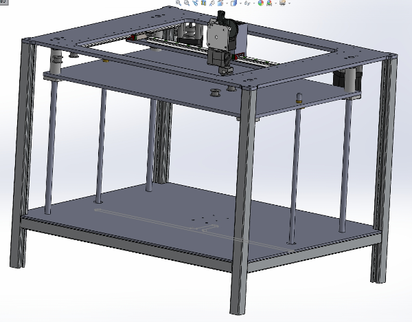
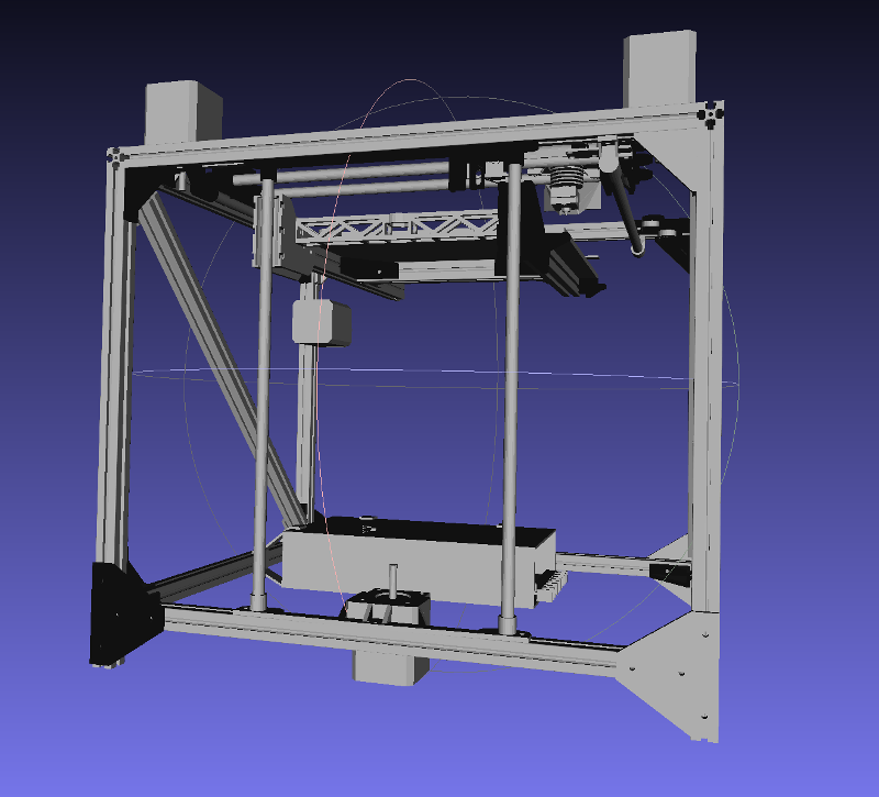
Here is a design where some advice was asked here http://forums.reprap.org/read.php?177,722199:
Analysing each face:
- The base is fantastic, it is entirely rigid. The bottom face therefore cannot "shear" (become a parallelogram).
- The top face is also excellent: the aluminium plate, despite having a hole for the X-Y assembly, is of sufficient thickness and the hole is no so large so as to reduce the rigidity of the aluminium plate as a frame, so as to provide complete rigidity in the top.
- However the open sides mean that the entire assembly may be "twisted" or "sheared": any one of the four sides may become a parallelogram, resulting in the entire frame being completely flexible.
Note that there are no corner braces in this design, on any of the uprights, so there is absolutely nothing to stop the twisting and shearing. "Twisting" may be demonstrated by securing the four feet of the cube to the floor, then taking the top and trying to "unscrew" the whole assembly as you would a jar's lid. With this type of cube design if any one side is left open, then like a cardboard box where the top is open, all efforts spent on rigidity of the other five cube sides are entirely wasted: it is essential that all six sides are made rigid.
So as described in the forum thread, fixing this design to make it rigid may be achieved by:
- Filling in all four remaining sides with some form of panel. Although acrylic or lexan provides internal visibility, even 3mm hardboard or MDF is sufficient for this purpose, and even 1.5mm plywood would suffice if, along the actual frame, the plywood is doubled up so as to spread the load of the bolts (with thin plywood, washers would be inadequate), and there are attachment points at least every 80-100mm on every single piece of the frame. Particular attention needs to be paid to ensure that there is good friction between the frame and the panel.
- If however there are large holes to be put in the panels (so as to provide visibility or access) then thin materials such as hardboard, MDF or plywood are not sufficient, not least because these cheaper materials are subject to expansion under different temperatures and humidity. Better materials would be aluminium or other metal, lexan, acrylic and so on. The required thickness of the panel with a large access hole will depend on the size of the printer. For a 200x200 printer a minimum of 5mm material should be considered and a minimum of 40mm border, with more than that at corners. A good example is the Ultimaker 2 (see below).
- Adding diagonal struts from corner to corner in all four faces, ensuring that the struts do actually go into the corners instead of some distance along one of the other frame pieces. Attaching the diagonals to both the horizontal and upright parts of the frame is best.
- Replacing the upright struts with much thicker extrusion (30x30, 40x40) and then ensuring that they are braced properly in the corners. This means using beefy triangular braces (40x40mm or greater) or drilling sideways through the extrusion and using an allen keyed hex bolt to attach it to the centre hole of the piece that it is to be attached to. For this particular trick to work the ends of the extrusions must be absolutely dead flat.
Ultimaker 2: no improvement needed
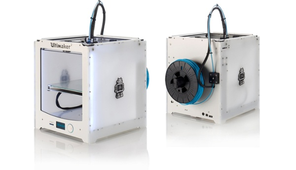
The Ultimaker 2 is an excellent example of a completely rigid cube design:
This design is superb. Every single one of the six faces is filled with panels that provide the full required set of rigidity for all six degrees of freedom.
- The top is a panel that looks to be a 40mm "picture frame" that is at least 4mm thick. If the hole gave a border less than 40mm then the panel could potentially start to flex and bow, thus defeating the purpose of it being present.
- The sides except the front (and probably the bottom as well) are entirely solid, providing excellent rigidity
- The front is again a panel that has an access hole, but the border is sufficiently large so as to not result in flexing.
- There are lots of attachment points between the panels, particularly in the corners, but also in the middle (to stop the panels bowing outwards).
Interestingly there are no internal struts: no extruded aluminium. The cube is entirely made from its panels. With this technique, as long as the assemblies within the cube are securely attached to all three panel faces then the assemblies are also constrained in all six degrees of freedom. If the assemblies themselves are also rigid then the assemblies, if placed in each corner, would double up as corner bracing for the panels.
Overall, this frame is a superb piece of engineering design.
Printbed Examples
Triple lead screws, dual rails
This type of design is discussed on the reprap forum here: http://forums.reprap.org/read.php?397,726304,766930 and the design files may be obtained here: https://www.youmagine.com/designs/2040-laser-cut-core-xy-v0-8
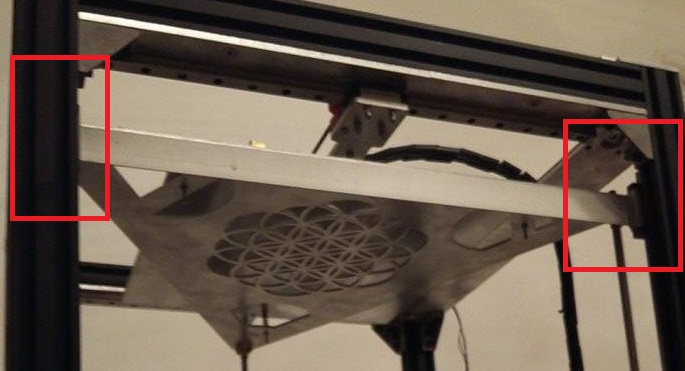
Note that this particular design's frame suffers from lack of rigidity (no side support, insufficient upright bracing - see above) however the bed support is excellent. Here is a photo highlighting the use of dual rails:
A six degrees of freedom analysis of this design is as follows:
- Triple lead screws stop X and Y rotation and control Z linear movement but do not prevent X or Y linear movement (sideways sliding) and do not prevent Z rotation (not least, the Z-screws can bend).
- Dual rails will stop X and Y linear movement, will permit the required Z linear movement, will stop Z rotation, and will stop EITHER X OR Y rotation (but not both). Specifically: without the lead screws, one rail could go up and the other could go down, causing the bed to rotate about the axis that's perpendicular to the two rails.
The COMBINATION of those two sets of contraints happens to provide the full set of required control over all six degrees of freedom.
Note that a single rail will not do the job, because the Z-screws can bend about the middle and the printbed could rotate around the centre of a single rail. Triple (or greater) rails would be redundant. Quadruple z-screws or greater would also be redundant.
For a moving bed like this, one or two lead screws are not sufficient: with only one or two lead screws the burden then falls onto the z-rails to prevent rotation in X Y and Z, and that places significant strain on the block.
Fusebox: inadequate 8mm rods, single lead screw, cantilevered bed with insufficient support
The Fusebox is a low-cost design that highlights a huge number of flaws with the average classic cantilevered printbed.
The flaws in this design are numerous:
- Firstly, the rods are only 8mm. With almost 250mm to the end of the printbed, a "lever" effect can create significant amounts of bend to adversely affect the quality of the print as weight accumulates on the printbed.
- Secondly, there is only a single lead screw with a distance between the rods of 140mm, spanned by a single piece of plastic only 20mm in height (and 130mm in length). This creates the possibility of a rotational moment about the Y-axis, where one linear bearing can go up whilst the other can go down. If a print is ever made off-centre on this design it will gradually push the printbed further down on that side and will no longer be straight!
- Thirdly, the 130x20mm horizontal piece between the rods and spanning that 140mm gap is simply not strong enough: it will bend under load.
- Fourthly: LM8LUU bearings, even at 45mm in length, are of insufficiently high quality machine tolerances to prevent rotation about the X-axis (drooping of the front of the printbed)
- Fiftly: the LM8LUU bearing holders are not sufficiently long - or strong - to be able to hold up the weight of the printbed itself.
This example therefore highlights a huge number of classic design mistakes with cantilevered printbeds that are sadly extremely common. To fix these issues, the following needs to be considered:
- Replacing the 8mm rods with at least 10mm (preferably 12mm) rods, or, better, going to linear rails attached firmly and properly to the aluminium frame, at least 20x20 in size. This ensures that there is no "bend" (flex).
- Use of an L-shaped piece of aluminium between the rods, and, if sticking to rods, using four blocks of high precision of the type which have four mounting points. The height of the L-shape should be at least 75mm so as to prevent rotation.
- Rigid (metal) triangular bracing struts on both sides, from the bottom of the L-shaped aluminium to the centre of the printbed.
- The L-shape of the aluminium plate has two effects: first it stops bending of the plate (without needing huge amounts of material) and second a hole may be drilled in the horizontal part so that the lead screw can be attached through it.
