Mechanical Rigidity
Contents
Mechanical Rigidity
This page goes into the basics, with illustrations, on how to ensure that a design is mechanically rigid, and also what to look for if buying an existing 3D printer. The key elements are:
- Rigidity must be achieved in all six degrees of freedom: Rotation ("twisting" or "screwing") about each of X, Y and Z, and Movement in X, Y and Z (shearing or "parallelogramming").
- The simplest rigid open structure is a triangle.
- Solid materials (plates, bars, extrusions, rods etc.) have rigidity that is proportional to their thickness (or length). Rods (or bars) in particular have lateral flex that is proportional to the square of their length.
- A "lever" effect on the way that two frame parts are connected together is critical to take into account. The further the distance the more critical the material strength of the parts (and their method of connection) becomes.
Frames
A quick guide to analysing an existing frame design is:
- If it is a cube design, is there support in all six faces of some kind? Either plates (polycarbonate, acrylic, plywood or hardboard at least 2.5mm thick) filling each face, diagonal struts that go fully to corners creating complete triangles, or even suitably strong (i.e. with no flex) very high-tension wires (again creating complete triangles to all vertices)
- If it is a Mendel style design, these are not rigid at all in their base, and rely completely on being on a flat surface, with gravity assisting to keep them down. This tends in practice to be ok, but it is not the only issue to watch out for.
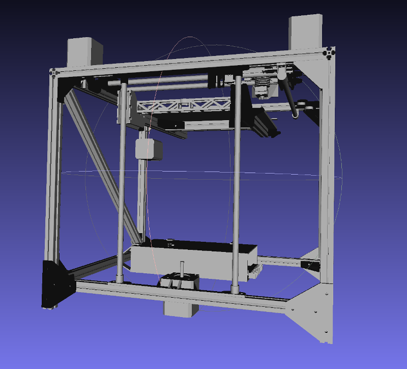
- If it is an "open design" without triangles (or plates), is the frame of sufficient thickness for the size (3030 or preferably 4040 for a 200x200 printer, to 8020 extrusion for a 300x300 or greater) and are the frame struts sufficiently strongly connected together?
- 3D-printed plastic, if used at corners as the sole method to join frame parts together, should be definitively considered a "red flag" that warrants full investigation and a thorough analysis.
- If you are concerned at all about rigidity affecting build quality, avoid Kossel (delta printers) entirely.
For further illustration, examples have been split into their own sub-page, with a quick summary on each:
- Mechanical_Rigidity/Mendel - inspiration for the 3D printing movement but deeply flawed.
- Mechanical_Rigidity/Mendel90 - significant improvement, still not perfect but in practice perfectly fine.
- Mechanical_Rigidity/MendelFlex - extremely well-engineered variant of the Mendel: a different approach from the Mendel90
- Mechanical_Rigidity/Cube_Example - good demonstration of the flaws and the complexity inherent in a cube design.
- Mechanical_Rigidity/Ultimaker_2 - the "Gold Standard" for any cube design.
- Mechanical_Rigidity/Original_Kossel - low cost but deeply flawed: no rigidity whatsoever.
- Mechanical_Rigidity/Fisher - how a Delta 3D printer should be done.
- Mechanical_Rigidity/Folgertech_Kossel_Bracing - good effort but a Delta's struts are too long for bracing to be effective
- Mechanical_Rigidity/Voxel_Ox_8020 - how to "beef up" a frame to good effect.
Printbeds
A quick guide to printbeds:
- Mendel style printbeds are fine: just watch out for the plate under the printbed being made of sufficiently rigid material (see printbed section for details)
- Cantilevered printbeds should have linear rails or V-rollers, and if rods are in use they should be at least 10mm preferably 12mm. Most cantilevered designs are severely problematic, and they all rely on the mechanical properties (amount of bend) of the materials used.
- With dual z-screws (centrally-cantilevered printbed), look for four linear bearings/blocks (two per rod/rail) or twin V-rollers per rail, to ensure that the bed cannot wobble about (rotate). Ensure that there is a rigid cross-bar (plate or other assembly) to which all four bearings / blocks / V-rollers are mounted.
- Kossel (delta) printer beds are fixed (and so are fine): it's the print-head rods that require micro-millimetre accuracy and are a huge headache to calibrate.
- The best (vertically-moving) printbed arrangement is by far and above triple (or greater) lead screws and dual (or greater) rails/rods (even if the rods - if rods are used - are only 8mm and only have one bearing/block/roller per rod/rail).
Mendel style printbeds
Mendel style printbeds have one significant advantage: they are flat, only move in one direction, and need only three bearings and two rods (see photos above of Mendel90). One thing to watch out for however, particularly on cheap-cost China clones, is the use of an inadequate thickness metal plate to which the bearings (and the Y-belt) are attached. For a 200x200mm Printbed, anything less than a 3mm aluminium plate, 6mm acrylic or 4mm dibond is going to be completely inadequately stiff, resulting in flexing of the plate (to which the printbed is attached), thus in turn adversely affecting build quality.
Print Bed Mounting: 3 or 4 points
Although it is considered unnecessary to have 4 mount points for bed levelling, one of the problems with printbeds is that sometimes they will be warped. Depending on the degree of warping, 4-point levelling allows the warping to be corrected, whereas if a triple-mounted printbed is warped it will need to be repaired or entirely replaced. Sourcing a triple-mounted printbed plate that is sufficiently thick and properly machined (and adequately packaged when shipping) is therefore critical.
Triple lead screws, dual rails
On its own page Mechanical_Rigidity/Triple_Lead_Dual_Support
Laser-cut acrylic / wood, single lead screw, dual rods cantilevered design
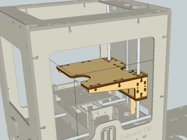
There is an innovative upgrade to the Cupcake CNC which is based around laser-cutting of thick acrylic / wood:
- The use of sturdy (6-8mm thick) laser-cut panels means that no bending / flexing will occur
- The rods look like they are either 10 or 12mm and there are two large bearings one under the other on one side
- The printbed is supported underneath on three sides so will not flex.
All in all this is a surprisingly good design, despite the left-hand rod only having one bearing where the other side has two. Improvements to this design would involve creating a full "box" structure entirely surrounding the bearings, expanding the depth of the box so that there is at least 70mm separation betweeen the bearings, and using four bearings (two per rod) instead of just three. This would ensure that both rods are used to prevent rotation about the Y-axis of the entire assembly, whereas in its current incarnation the right-most rod with two bearings is exclusively responsible for preventing rotation.
Fusebox: inadequate 8mm rods, single lead screw, cantilevered bed with insufficient support
The Fusebox is a low-cost design that highlights a huge number of flaws with the average classic cantilevered printbed.
The flaws in this design are numerous:
- Firstly, the rods are only 8mm. With almost 250mm to the end of the printbed, a "lever" effect can create significant amounts of bend to adversely affect the quality of the print as weight accumulates on the printbed.
- Secondly, there is only a single lead screw with a distance between the rods of 140mm, spanned by a single piece of plastic only 20mm in height (and 130mm in length). This creates the possibility of a rotational moment about the Y-axis, where one linear bearing can go up whilst the other can go down. If a print is ever made off-centre on this design it will gradually push the printbed further down on that side and will no longer be straight!
- Thirdly, the 130x20mm horizontal piece between the rods and spanning that 140mm gap is simply not strong enough: it will bend under load.
- Fourthly: LM8LUU bearings, even at 45mm in length, are of insufficiently high quality machine tolerances to prevent rotation about the X-axis (drooping of the front of the printbed) and the Y-axis (wobbling printbed, side-to-side).
- Fiftly: the LM8LUU bearing holders are not sufficiently long - or strong - to be able to hold up the weight of the printbed itself: the plastic of the bearing holders will therefore bow under the weight, causing inaccurate printing.
This example therefore highlights a huge number of classic design mistakes with cantilevered printbeds that are sadly extremely common. To fix these issues, the following needs to be considered:
- Replacing the 8mm rods with at least 10mm (preferably 12mm) rods, or, better, going to linear rails attached firmly and properly to the aluminium frame, at least 20x20 in size. This ensures that there is no "bend" (flex).
- Use of an L-shaped piece of aluminium between the rods, and, if sticking to rods, using four blocks of high precision of the type which have four mounting points. The height of the L-shape should be at least 75mm so as to prevent rotation.
- Rigid (metal) triangular bracing struts on both sides, from the bottom of the L-shaped aluminium to the centre of the printbed.
- The L-shape of the aluminium plate has two effects: first it stops bending of the plate (without needing huge amounts of material) and second a hole may be drilled in the horizontal part so that the lead screw can be attached through it.

