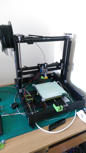
Mechanical Rigidity/Voxel Ox 8020
Voxel Ox: 8020 frame parts
In this thread the use of 8020 frame parts is demonstrated: http://forums.reprap.org/read.php?177,702346,702528#msg-702528
This design has a number of improvements over the basic Mendel:
- The base is made from four 8020 extrusions that are joined together with double 20x20 triangles per corner.
- The base also appears to be braced across the middle, preventing parallelogramming.
- The uprights, by also being 8020 and being attached on both sides, will also not rotate about the X-Axis.
- The top support for the Z motor will therefore not rotate about the Z-axis
- The build plate is again mounted on 8020 extrusion, which should not be going anywhere: it appears to be fixed with double 20x20 triangles in at least three points, with one being a (green) 3D-printed part.
However despite the beefy use of 8020 extrusion there are still a couple of flaws:
- The base can still be lifted at one corner whilst the other three remain on the ground. However in reality the amount by which this frame would actually twist should be absolutely minimal, but just to be safe it would be best operated on a rigid absolutely dead-flat surface.
- The uprights may still "parallelogram" (shear sideways). However looking closely at the X-Carriage it appears to have rollers on a plate that is upright (and firmly attached to the two X-carriage extrusions) that might assist in reducing sideways shear, but potentially at the cost of damaging the rollers. In reality though this printer would have to be operated at extreme speeds (and the objects being printed very tall) for there to be any problems.
Fixing this latter problem would involve extending the uprights a good 75mm above the top horizontal assembly, then attaching two beefy aluminium triangular plates at each corner (minimum 75mm size). The reason for extending the uprights is because if triangular bracing was added underneath it would interfere with the maximum build height, as the sides of this particular design are used for running rollers. Alternatively the top extrusion could be extended outwards, and multiple 40x40 triangles on each upright utilised to achieve the same effect.
Overall however this is a really good design.
