Mendel90 Build Manual
Contents
Bill of Materials
The latest version can be found here: https://raw.github.com/nophead/Mendel90/master/mendel/bom/bom.txt
Vitamins:
                                                Z

                                                l
D        E                                      i
         l              X           Y           m
c        e                                      i
o        c              c           c           t
n     B  t     M        a  X  X     a  Y  Y        Z
n     e  r     a     X  r        Y  r        Z  s
e     d  o  F  c  W     r  i  m     r  i  m     w  m
c        n  r  h  a  a  i  d  o  a  i  d  o  a  i  o
t  B  f  i  a  i  d  x  a  l  t  x  a  l  t  x  t  t
o  e  a  c  m  n  e  i  g  e  o  i  g  e  o  i  c  o
r  d  n  s  e  e  s  s  e  r  r  s  e  r  r  s  h  r
 |  |  |  | 1|  |  |  |  |  |  |  |  |  |  |  |  |  |  1 Acrylic sheet 468mm x 432mm x 10mm
 |  |  |  | 2|  |  |  |  |  |  |  |  |  |  |  |  |  |  2 Acrylic sheet 170mm x 324mm x 6mm
 |  |  |  |  |  |  |  |  |  |  |  | 1|  |  |  |  |  |  1 Acrylic sheet 224mm x 224mm x 6mm
 |  |  |  | 1|  |  |  |  |  |  |  |  |  |  |  |  |  |  1 Acrylic sheet 468mm x 324mm x 6mm
 |  |  |  |  |  |  |  |  |  |  |  | 5|  |  |  |  |  |  5 Aluminium foil tape 50mm x 234mm x 0.05mm
 |  |  |  |  |  | 3|  |  |  |  |  |  |  |  |  |  |  |  3 Ball bearing 608 8mm x 22mm x 7mm
 |  |  |  |  |  |  |  |  | 1|  |  |  | 2|  |  |  |  |  3 Ball bearing 624 4mm x 13mm x 5mm
 | 4|  |  |  |  |  |  |  |  |  |  |  |  |  |  |  |  |  4 19mm bulldog clip
 | 1|  |  |  |  |  |  |  |  |  |  |  |  |  |  |  |  |  1 PCB bed 214mm x 214mm
 |  |  |  |  |  |  |  |  |  |  | 1|  |  |  |  |  |  |  1 Belt T5 x 6mm x 674mm
 |  |  |  |  |  |  | 1|  |  |  |  |  |  |  |  |  |  |  1 Belt T5 x 6mm x 866mm
 |  |  |  |  |  |  |  |  |  |  |  | 1|  |  |  |  |  |  1 Corrugated cardboard 200mm x 224mm x 6mm
 | 4|  | 4|  |  |  |  |  |  |  |  |  |  |  |  |  |  |  8 M3 cap screw x 10mm
2|  |  | 4|  |  |  |  |  |  | 2| 4|14|  |  | 2|  | 2| 30 M3 cap screw x 16mm
2|  |  |  |  |  |  |  | 1|  |  |  |  |  |  |  |  | 8| 11 M3 cap screw x 20mm
 |  |  |  |  |  |  |  | 2|  |  |  | 2|  |  |  |  |  |  4 M3 cap screw x 25mm
 |  |  |  |  |  | 2|  |  |  |  |  |  |  |  |  |  |  |  2 M3 cap screw x 30mm
2|  |  |  |  |  |  |  |  |  |  |  |  |  |  |  |  |  |  2 M3 cap screw x 45mm
 |  | 4|  |  |  |  |  |  |  |  |  |  |  |  |  |  |  |  4 M4 cap screw x 20mm
 |  |  |  |  |  |  |  |  | 1|  |  |  | 1|  |  |  |  |  2 M4 cap screw x 40mm
1|  |  |  |  |  |  |  |  |  |  |  |  |  |  |  |  |  |  1 9 way D plug
1|  |  |  |  |  |  |  |  |  |  |  |  |  |  |  |  |  |  1 9 way D socket
 |  | 1|  |  |  |  |  |  |  |  |  |  |  |  |  |  |  |  1 Fan 80mm x 38mm
 |  |  |  |  |  | 1|  |  |  | 1|  |  |  | 1|  |  |  |  3 M3 grub screw x 6mm
 | 1|  |  |  |  |  |  |  |  |  |  |  |  |  |  |  |  |  1 Glass sheet 214mm x 202mm x 2mm
 | 4|  |  |  |  |  |  |  |  |  |  |  |  |  |  |  |  |  4 Hex pillar M3 x 20mm
 |  |  |  |  |  |  |  |  | 2| 4|  |  |  |  |  | 1|  |  7 M3 hex screw x 16mm
 |  |  |  |  |  | 2|  |  |  |  |  |  |  |  |  |  |  |  2 M4 hex screw x 20mm
 |  |  |  |  |  | 2|  |  |  |  |  |  |  |  |  |  |  |  2 M4 hex screw x 50mm
 |  |  |  |  |  | 1|  |  |  |  |  |  |  |  |  |  |  |  1 M8 hex screw x 60mm
 |  |  | 1|  |  |  |  |  |  |  |  |  |  |  |  |  |  |  1 PSU e.g. KY240W12L
 |  |  |  |  |  |  |  | 3| 2| 2|  | 3|  |  |  |  |  | 10 LM8UU linear bearing
 |  |  |  |  |  | 1|  |  |  | 1|  |  |  | 1|  |  | 2|  5 NEMA17 x 47.5mm stepper motor
2|  |  |  |  |  | 1|  | 1|  | 1|  |  |  | 1|  |  |  |  6 Nut M3
 |  |  |  |  |  | 2|  |  |  |  |  |  |  |  |  |  |  |  2 Nut M4
 |  |  |  |  |  | 1|  |  | 1| 1|  |  |  |  |  |  |  |  3 Nut M8
2|  |  |  |  |  |  |  | 2| 2| 6| 4|16|  |  | 2| 1|10| 45 Nyloc nut M3
 |  | 4|  |  |  |  |  |  | 1|  |  |  | 1|  |  |  |  |  6 Nyloc nut M4
 |  |  |  |  |  |  | 1|  |  |  |  |  |  |  |  |  |  |  1 Polypropylene strip 402mm x 17mm x 0.5mm
 |  |  |  | 1|  |  |  |  |  |  |  |  |  |  |  |  |  |  1 Polypropylene strip 320mm x 27mm x 0.5mm
 |  |  |  | 1|  |  |  |  |  |  |  |  |  |  |  |  |  |  1 Polypropylene strip 275mm x 29mm x 0.5mm
 |  |  |  |  |  | 3|  |  |  | 3|  |  |  | 4|  |  | 8| 18 M3 pan screw x 8mm
 |  |  |  |28|  |  |  |  |  |  |  |  |  |  | 4| 2| 4| 38 M4 pan screw x 12mm
 |  |  |  |11|  |  |  |  |  |  | 8|  | 1| 4|  |  |  | 24 M4 pan screw x 16mm
4|  |  |  |  |  |  |  |  |  | 2| 2|  |  |  | 2| 2|  | 12 No2 pan wood screw x 13mm
 |  |  |  |  |  | 1|  |  |  |  |  |  |  |  |  |  |  |  1 Smooth rod 8mm x 22mm
 |  |  |  |  |  |  |  |  |  |  | 1|  |  |  |  |  |  |  1 Smooth rod 8mm x 270mm
 |  |  |  |  |  |  |  |  |  |  |  |  |  |  | 2|  |  |  2 Smooth rod 8mm x 275mm
 |  |  |  |  |  |  | 2|  |  |  |  |  |  |  |  |  |  |  2 Smooth rod 8mm x 382mm
 |  |  |  |  |  |  |  |  |  |  | 1|  |  |  |  |  |  |  1 Smooth rod 8mm x 428mm
 |  |  | 1|  |  |  |  |  |  |  |  |  |  |  |  |  |  |  1 Electronics e.g. Sanguinolou
 |  |  |  |  |  |  |  |  |  | 1| 1|  |  |  | 1| 1|  |  4 Microswitch
 |  |  |  |  |  | 1|  |  |  |  |  |  |  |  |  |  |  |  1 Spring 12mm OD x 0.75mm gauge x 10mm length
 |  |  |  |  |  | 2|  |  |  |  |  |  |  |  |  |  |  |  2 Spring 7mm OD x 1mm gauge x 10mm length
 |  |  |  |  |  |  |  |  |  |  |  |  |  |  | 2|  |  |  2 Threaded rod M8 x 211mm
 |  |  |  |  |  |  |  |  |  |  |  |  |  |  |  |  | 2|  2 Tubing OD 7mm ID 5mm x 16mm
4|  |  |  |  |  |  |  |  |  | 2| 2|  |  |  | 2| 2|  | 12 Washer M2.5 x 5mm x 0.5mm
8| 2|  | 8|  |  | 3|  | 2| 2| 9| 4|24|  | 4| 2| 1|18| 87 Washer M3 x 7mm x 0.5mm
 |  | 4|  |39|  | 2|  |  | 2|  | 8|  | 5| 4| 4| 2| 4| 74 Washer M4 x 9mm x 0.9mm
 |  |  |  |  |  |  |  |  | 2|  |  |  | 2|  |  |  |  |  4 Washer M5 x 20mm x 1.4mm
 |  |  |  |  |  | 1|  |  |  |  |  |  |  |  |  |  |  |  1 Washer M8 x 16mm x 1.5mm
 |  |  |  |  |  |  |  | 2|  |  |  |  |  |  |  |  |  |  2 Wingnut M4
 |  |  |  |  |  |  |  |  |  |  |  |  |  |  |  | 2|  |  2 Rubber washer M3 x 10mm x 1.5mm
 |  |  | 8|  |  | 3|  |  |  | 3|  |  |  | 4|  |  | 8| 26 Star washer M3 x 7mm x 0.5mm
 |  |  |  |30|  |  |  |  |  |  | 8|  | 1| 4| 4| 2| 4| 53 Star washer M4 x 9mm x 0.9mm
 |  |  |  |  |  |  |  | 3|  |  |  | 3|  |  |  |  |  |  6 Ziptie 87mm min length
Printed:
 |  |  |  | 2|  |  |  |  |  |  |  |  |  |  |  |  |  |  2 cable_clip_AB.stl
 |  |  |  | 2|  |  |  |  |  |  |  |  |  |  |  |  |  |  2 cable_clip_AD.stl
 |  |  |  | 1|  |  |  |  |  |  |  |  |  |  |  |  |  |  1 cable_clip_CA.stl
1|  |  |  |  |  |  |  |  |  |  |  |  |  |  |  |  |  |  1 d_motor_bracket.stl
1|  |  |  |  |  |  |  |  |  |  |  |  |  |  |  |  |  |  1 d_motor_bracket_lid.stl
1|  |  |  |  |  |  |  |  |  |  |  |  |  |  |  |  |  |  1 d_shell.stl
1|  |  |  |  |  |  |  |  |  |  |  |  |  |  |  |  |  |  1 d_shell_lid.stl
 |  | 1|  |  |  |  |  |  |  |  |  |  |  |  |  |  |  |  1 fan_guard.stl
 |  |  |  |10|  |  |  |  |  |  |  |  |  |  |  |  |  | 10 fixing_block.stl
 |  |  | 4|  |  |  |  |  |  |  |  |  |  |  |  |  |  |  4 pcb_spacer.stl
 |  |  |  |  |  |  |  |  |  | 1|  |  |  | 1|  |  |  |  2 pulley.stl
1|  |  |  |  |  |  |  |  |  | 1|  |  |  |  |  |  |  |  2 ribbon_clamp_12_33.stl
 |  |  |  |  |  |  |  |  |  | 1|  |  |  |  |  |  |  |  1 ribbon_clamp_20_33.stl
 |  |  |  | 1|  |  |  |  |  |  |  |  |  |  |  |  |  |  1 ribbon_clamp_20_44.stl
 |  |  |  |  |  |  |  |  |  |  |  | 2|  |  |  |  |  |  2 ribbon_clamp_22_33.stl
 |  |  |  | 1|  |  |  |  |  |  |  |  |  |  |  |  |  |  1 ribbon_clamp_22_44.stl
 |  |  |  |  |  | 1|  |  |  |  |  |  |  |  |  |  |  |  1 wades_big_gear.stl
 |  |  |  |  |  | 1|  |  |  |  |  |  |  |  |  |  |  |  1 wades_block.stl
 |  |  |  |  |  | 1|  |  |  |  |  |  |  |  |  |  |  |  1 wades_gear_spacer.stl
 |  |  |  |  |  | 1|  |  |  |  |  |  |  |  |  |  |  |  1 wades_idler_block.stl
 |  |  |  |  |  | 1|  |  |  |  |  |  |  |  |  |  |  |  1 wades_small_gear.stl
 |  |  |  |  |  |  |  | 1|  |  |  |  |  |  |  |  |  |  1 x_belt_clamp.stl
 |  |  |  |  |  |  |  | 1|  |  |  |  |  |  |  |  |  |  1 x_belt_grip.stl
 |  |  |  |  |  |  |  | 1|  |  |  |  |  |  |  |  |  |  1 x_belt_tensioner.stl
 |  |  |  |  |  |  |  | 1|  |  |  |  |  |  |  |  |  |  1 x_carriage.stl
 |  |  |  |  |  |  |  |  | 1|  |  |  |  |  |  |  |  |  1 x_idler_bracket.stl
 |  |  |  |  |  |  |  |  |  | 1|  |  |  |  |  |  |  |  1 x_motor_bracket.stl
 |  |  |  |  |  |  |  |  |  |  | 3|  |  |  |  |  |  |  3 y_bar_clamp.stl
 |  |  |  |  |  |  |  |  |  |  | 1|  |  |  |  |  |  |  1 y_bar_clamp_switch.stl
 |  |  |  |  |  |  |  |  |  |  |  | 2|  |  |  |  |  |  2 y_bearing_mount.stl
 |  |  |  |  |  |  |  |  |  |  |  | 1|  |  |  |  |  |  1 y_bearing_mount_switch.stl
 |  |  |  |  |  |  |  |  |  |  |  | 1|  |  |  |  |  |  1 y_belt_anchor.stl
 |  |  |  |  |  |  |  |  |  |  |  | 1|  |  |  |  |  |  1 y_belt_anchor_toothed.stl
 |  |  |  |  |  |  |  |  |  |  |  | 1|  |  |  |  |  |  1 y_belt_clip.stl
 |  |  |  |  |  |  |  |  |  |  |  | 1|  |  |  |  |  |  1 y_belt_clip_toothed.stl
 |  |  |  |  |  |  |  |  |  |  |  |  | 1|  |  |  |  |  1 y_idler_bracket.stl
 |  |  |  |  |  |  |  |  |  |  |  |  |  | 1|  |  |  |  1 y_motor_bracket.stl
 |  |  |  |  |  |  |  |  |  |  |  |  |  |  | 1|  |  |  1 z_bar_clamp.stl
 |  |  |  |  |  |  |  |  |  |  |  |  |  |  | 1|  |  |  1 z_bar_clamp_switch.stl
 |  |  |  |  |  |  |  |  |  |  |  |  |  |  |  |  | 4|  4 z_coupling.stl
 |  |  |  |  |  |  |  |  |  |  |  |  |  |  |  | 1|  |  1 z_limit_switch_bracket.stl
 |  |  |  |  |  |  |  |  |  |  |  |  |  |  |  |  | 1|  1 z_motor_bracket_lhs.stl
 |  |  |  |  |  |  |  |  |  |  |  |  |  |  |  |  | 1|  1 z_motor_bracket_rhs.stl
 |  |  |  |  |  |  |  |  |  |  |  |  |  |  | 2|  |  |  2 z_screw_pointer.stl
Sub-assemblies:
 1 D_connector_assembly
 1 bed_assembly
 1 bed_fan_assembly
 1 electronics_assembly
 1 frame_assembly
 1 machine_assembly
 1 wades_assembly
 1 x_axis_assembly
 1 x_carriage_assembly
 1 x_idler_assembly
 1 x_motor_assembly
 1 y_axis_assembly
 1 y_carriage_assembly
 1 y_idler_assembly
 1 y_motor_assembly
 1 z_axis_assembly
 1 z_limit_switch_assembly
 2 z_motor_assemblies
Printed Parts
The STLs are links to GitHub, so they are always the latest version. Follow the link and then right click on "RAW" and do "Save As" to download an individual STL. For multiple files the whole project can be downloaded as a Zip from GitHub.
Required
| Quantity | Description | File | Picture |
|---|---|---|---|
| 1 | Bar Clamps | stl | 
|
| 1 | Cable Clips | stl | 
|
| 10 | Fixing Blocks | stl | 
|
| 2 | Pulleys | stl | 
|
| 1 | Ribbon Clamps | stl | 
|
| 1 | X Carriage | stl | 
|
| 1 | X Idler | stl | 
|
| 1 | X Motor Bracket | stl | 
|
| 1 | Y Bearing Mounts | stl | 
|
| 1 | Y Belt Anchors | stl | 
|
| 1 | Y Idler Bracket | stl | 
|
| 1 | Y Motor Bracket | stl | 
|
| 4 | Z Coupling | stl | 
|
| 1 | Z Motor Bracket | stl | 
|
Modified Wade's Geared Extruder
| Quantity | Description | File | Picture |
|---|---|---|---|
| 1 | Extruder Body | stl | 
|
| 1 | Small Gear | stl | 
|
| 1 | Large Gear | stl | 
|
| 1 | Cable Mount | stl | 
|
Optional
| Quantity | Description | File | Picture |
|---|---|---|---|
| 1 | Fan Guard-If you have a fan | stl | 
|
| 4 | PCB spacers | stl | 
|
| 2 | Z Pointers | stl | 
|
So far the parts have only been tested in ABS.
The latest STL files are on GitHub at github.com/nophead/Mendel90/tree/master/mendel/stls/printed. These are for the default "mendel" configuration. The STLs for the "sturdy" version are also there: github.com/nophead/Mendel90/tree/master/sturdy/stls/printed. For other configurations build the STL files from source using the scripts provided.
NopHead prints the gears, pulleys and cable clips with a 0.35mm nozzle using 0.3mm layers. The pulleys don't fit the belt well when printed with a bigger nozzle, even at the same layer height, because the teeth become too rounded. The gears can be printed with a 0.4mm nozzle but the M8 nut will be tight to press in because the corners of the hexagon get too rounded.
All the other parts are printed with a 0.4mm nozzle and 0.4mm layers. The W/T ratio is 1.5 in both cases. These parameters are defined in the config.scad file and affect the minimum horizontal and vertical feature sizes. Changing them will affect all the printed parts and sheet drawings slightly.
The relationship between nozzle size and maximum layer height depends on die swell, which in turn depends on the plastic and the length of the nozzle hole, so your mileage may vary.
The recommended infill density settings are as follows: -
| Fixing blocks, Wades block, Wades idler block, Wades small gear | 95% |
| Y bearing mounts, Z couplings | 75% |
| Z motor brackets | 75% hex |
| Bar clamps, Y belt anchors, Y idler bracket | 50% |
| X carriage, Y motor bracket | 50% hex |
| X idler bracket, X motor bracket | 25% hex |
| Everything else | 25% |
Printed with these setting the parts weigh about 400g, a little less than a Prusa. There are a lot more parts, but most are a lot smaller.
Most of the holes are Polyholes, so they should come out the right size on a well calibrated printer. The pulley and small gear holes are deliberately undersized to allow them to be reamed to exactly 5mm. cal.stl is a calibration object for testing hole sizes.
Parts which have holes in surfaces where there is nothing underneath have a support membrane that needs removing. The 8mm holes in the X ends and Wades block plus the rectangular hole in the top of the X motor bracket are best removed with a small knife. The smaller holes in the Y belt anchors, Z couplers and the X carriage are best cleared with a 3mm drill.
General tips
- All screws have a plain washer where they meet the plastic to spread the load and prevent the plastic being chewed up by the rotation of the screw head. Most fixings have a captive Nyloc nut to prevent them vibrating loose. You can use plain nuts but in that case you should add a star washer between the screw head and the plain washer. The screws into the panels have star washers for the same reason.
- If you are worried about the plastic nut traps being strong enough for Nylocs you can thread the Nyloc onto a spare screw first to loosen it. Nophead hasn't found this necessary.
- Washers tend to have a smooth side and a side with a burr from being stamped out. Make sure the smooth side faces bearings and belts.
- Chamfer the ends of the rods with a file to remove any burr, otherwise they can knock the balls out of the linear bearings.
Frame assembly
If you cut the frame parts out of a sheet of MDF with just simple tools: the original sheet very likely has pretty square corners. Cut the parts in such a way that the original square corners of the sheet are in the most important spots. A sheet of MDF of 2 by 4 feet (61x122cm) is enough for a Mendel sized Mendel90.
Drill and cutting guides
The PDF files of the sheets contain marked positions for all holes to be drilled. These PDFs can be printed on normal sized paper (A4 or Letter). To print the files: open the PDF in Adobe Reader, select: File -> Print. Choose "Poster" and select "Cut marks". This will print the drilling guide on a number of sheets of paper which can easily be glued or taper together.
Z axis
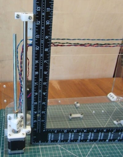
Use a large set square to ensure the left hand Z bar is vertical.
Y axis
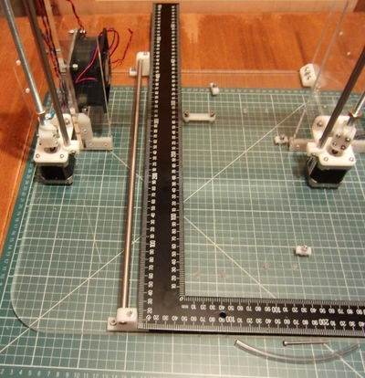
Fit the long Y bar first and use a large set square to make it perpendicular to the base sheet before tightening the base screws.
Y Heat Shield
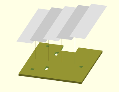
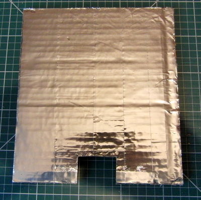
The heatshield prevents heat radiating downwards from the bed heating the Y carriage, which can make it warp due to the top surface expanding more than the bottom. 6mm corrugated cardboard is used as a cheap and effective insulator and aluminium foil tape on top reflects heat back towards the bed.
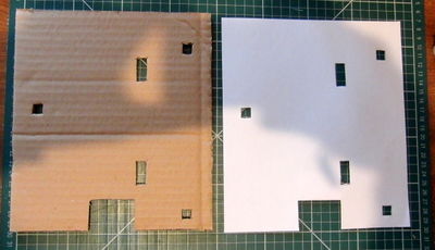
Start by printing a paper template from the pdf drawing https://github.com/nophead/Mendel90/raw/master/mendel/sheets/y_heatshield.pdf. Cut out the outline with scissors or a craft knife. Place the template over the cardboard and cut round with a straight edge and craft knife. Cut through the holes.
Apply the tape strips with some overlap. Turn it foil side down and trim round with a knife.
X axis
Wiring
Y & Z axis wiring
The motor wires should be tightly twisted in pairs to reduce RFI. The normal coil pairings for the recommended SY42STH47-1684A motors are red / blue and black / green. The easiest way to twist them is to tie a knot at the far end of the wire pair and spin it in the chuck of a drill with some tension on the wire.
The motors come with 2.5m of wire so it is best the cut them roughly to length before twisting them, but leave at least 0.5m spare to account for it getting shorter when twisted.
The spare wire can be used for the limit switches, fan and thermistor. Use different colour pairs to make them easily distinguishable from the motor wires and each other, e.g. red / black for the fan and green / blue for the limit switches. They should also be twisted to reduce induced noise.
The wires should be soldered to the limit switches before the switches are fitted. Use the outer two pins for normally closed.
There are three sizes of cable clip, each with two slots. The largest is for the bed and thermistor wires. The smallest is for the Y axis motor and limit switch. The middle size clips are for the Z axis motor + fan wires and the Z - limit switch.
The clips keep the sensitive input wires away from the power wires and there are separate holes in the frame which line up with the clips.
Bed wiring
The bed is connected via a 22 way ribbon cable.
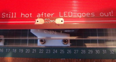
The pads on the bed are too small for the size of wire that is appropriate for the current, so remove some of the solder resist by scraping with a sharp blade. Scrape towards the edge to avoid the risk of damaging the finer heating tracks.
Block the holes on the back with some tape to prevent solder flowing through. Strip about 12mm of the outer ten wires on each side and twist them tightly together and solder to the pads.
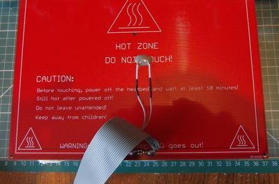
The middle two wires should be soldered to the thermistor leads. Keep the thermistor leads full length (because the are less thermally conductive than copper wires) and insulate them with PTFE sleeving. Use heatshrink sleeving over the solder joints.
Glue the thermistor to the underside of the bed using a thermally conductive high temperature glue such as JB-Weld, or tape it on with a high temperature tape such as Kapton, or the aluminium foil tape used for the heatshield.
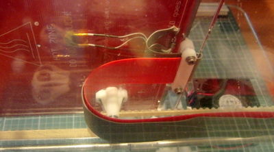
Note that the ribbon cable leads off towards the centre of the bed initially and then curls back towards the edge. Put the cable through the top ribbon clamp on Y carriage and screw the bed to the pillars. Loop the cable back underneath the carriage through the bottom ribbon clamp and put the cable strip underneath it in the same clamp.
Slide in the heatshield from the front and fix it front and back with high temperature tape.
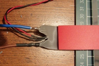
Terminate the ribbon cable just past the end of the cable strip as shown below. The thermistor connection can be made with left over motor wire. The bed wires should be 40 strands of 0.2mm, e.g. 13A mains cable.
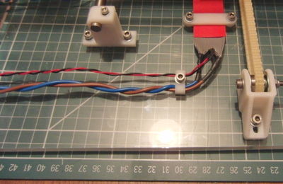
Fasten the free end of the ribbon cable and the cable strip to the base using the ribbon clamp. The strip should press against the cable to force it into a smooth loop. Use the cable clip to take the wires through a 90° bend and feed them through the holes in the right hand stay.
The suggested wiring sequence for least thermistor noise is : -
| Wire number | Signal |
|---|---|
| 1-10 | Heater - |
| 11 | Thermistor GND |
| 12 | Thermistor signal |
| 13-22 | Heater +12V |
X axis wiring
The X axis motor and the extruder are connected by a single 20 way ribbon cable. The following pin connections are used to minimise cross talk.
| Wire number | Signal | D type connector pin |
|---|---|---|
| 1 | Extruder motor black | Pin 5 |
| 2 | Extruder motor green | Pin 9 |
| 3 | Extruder motor blue | Pin 4 |
| 4 | Extruder motor red | Pin 8 |
| 5,6 | Heater - | Pin 3 |
| 7 | Fan - | Pin 7 |
| 8,9 | +12V | Pin 2 |
| 10 | Spare | |
| 11 | Thermistor GND | Pin 6 |
| 12 | Thermistor signal | Pin 1 |
| 13 | X limit GND | |
| 14 | X limit signal | |
| 15 | Guard loop GND | |
| 16 | Guard loop GND | |
| 17 | X motor red | |
| 18 | X motor blue | |
| 19 | X motor green | |
| 20 | X motor black |
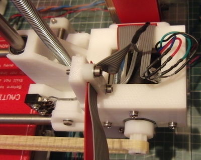
Start with about 1.5m of 20 way ribbon cable and put it through the ribbon clamps of the X motor bracket. Split off 12 ways and solder them to the D type connector. Pull the other ways back to the X end. Leave two long enough to go through the hole to the X limit switch and cut the rest just long enough to connect to the motor.
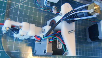
Attach the ribbon clamp at the extruder connector to trap both the wire and the polypropylene cable strip. Form it into a loop to reach the extruder before tightening the ribbon clamp at the X motor end.
Make the connections to the motor and limit switch and then fit the switch.
Note the two guard wires linked together and insulated.
Tuck the connected wires into the hole in the the bracket.
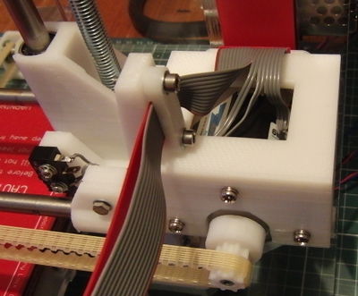
Fit the remaining cable strip and tighten the two 20 way ribbon clamps. The ribbon cable goes over the top and down into the electronics bay where all the other wires terminate.
Connecting the electronics
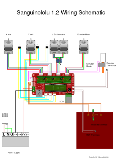
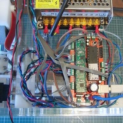
Fit your preferred electronics and connect all the wires. The example below shows a Sanguinololu connected as shown here:
Note:
- It could be a lot neater if the ribbon cable had not been cut too short and the other wires too long.
- The standard connectors have been replaced by screw connectors and ferrules as Nophead finds these more reliable.
- The X, Y and Z motors are wired in reverse compared to the diagram above because the motors are all reversed compared to a Prusa.
- The bed is connected directly to the PSU and the tab of the MOSFET with a ring terminal to avoid the underrated connector on the PCB.
- There is nowhere for the fan to connect on a Sanguinololu.
- The mains connections to the PSU should be completely covered and the cable should have strain relief, TBD.
Extruder wiring
The thermistor and heater wires should be kept at full length to minimise the temperature at the solder joints. PTFE sleeving and PTFE insulated wires are used close to the extruder to handle the temperature. Preferably the heat shrink sleeving should be silicone. The black heat shrink will degrade at hot end temperatures and can't be relied upon as insulation, so the heater joints are made inside the PTFE sleeving.
