Mendel USB and power connector/de
Hinweis: Dies wird eine Übersetzung der englischen Seite http://objects.reprap.org/wiki/Mendel_USB_and_power_connector.
Einführung

Diese Seite beschreibt, wie die Stromversorgung und die USB-Verbindung-vom-Computer am RepRap Version II "Mendel" angeschlossen werden.
Die USB- und Stromversorgungsanschlüsse des RepRaps sind links an der Rückseite der Maschine übereinandergestapelt. Im Bild rechts ist dies aus der Nähe dargestellt. Die beiden Steckverbinder sind auf der Platte montiert, an der auch die Schrittmotor-Treiberplatinen befestigt sind.
Die Stromversorgung für den RepRap
RepRap braucht eine 12-Volt-Stromversorgung, die mindestens 5 Ampere liefern kann. Du kannst entweder ein fertiges Netzteil mit diesen Leistungsdaten kaufen, was dann ordentlich aussieht, oder Du kannst ein altes PC-Netzteil umbauen, was sehr billig ist, aber dann etwas unaufgeräumt aussieht. Du kannst RepRap auch an einer 12-Volt-Autobatterie betreiben, oder den 12-Volt-Anschluss am Armaturenbrett (Zigarattenanzünder) verwenden.
Der Standard-Steckverbinder für den 12-V-Stromanschluss beim RepRap ist ein XLR-Steckverbinder.

Das vorstehend gezeigte Bild ist eine Sicht auf die Pins der Buchse ("Female" = weiblich) und des Steckers ("Male" = männlich). Pin 1 ist der Masseanschluss (Ground = Minuspol) und Pin 2 ist der +12V-Anschluss. Pin 3 wird nicht verwendet. Beim Mendel ist ein männlicher Steckverbinder an der Platte montiert. Die beiden Leitungen vom Netzteil werden an die Buchse angeschlossen, die an diesen Stecker angesteckt wird.

Der USB-Anschluss zum RepRap

You'll also need a USB to TTL converter so your computer can drive your RepRap via one of its USB ports. The picture shows the converter wired up and ready to be attached to the RepRap machine. Do this attachment as the very last part of putting your RepRap machine together. You can use this cable loose for testing and set-up; indeed, it's much easier to test and set up the machine with this cable unattached.
You will need an FT232RL UM232R USB to Serial UART Development Module from Future Technology Devices International Ltd. (alternatively, see the bottom of this page for a simpler, though less neat, alternative). The FT232RL UM232R is the green PCB that you can see in the picture. It handles all the transactions between the USB bus and the computer, and gives you a simple serial interface at the back-end that you can connect directly to the RepRap Motherboard that is controlling your RepRap machine. For those based in the USA, Sparkfun has some small boards at a good price.Sparkfun Boards
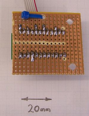
- Start by cutting a 40mm x 45mm rectangular piece of 2.54mm-pitch stripboard. Drill two 4mm holes 30mm apart at one end as shown, and two 3mm holes near one edge 12 mm apart again as shown (with the blue cable tie). Cut all the tracks down the middle as in the photograph, and the 5th track in on the 4mm hole end, also as shown (these last are to prevent the 4mm nuts shorting out the FT232RL UM232R). Solder the FT232RL UM232R to the stripboard, with its USB 'B' connector at the end with the 4mm holes. The end of the connector should be just flush with the edge of the stripboard.
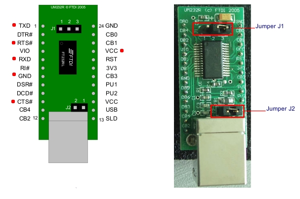
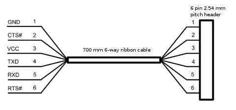
- Cut an 700 mm length of 6-way ribbon cable, split off the six wires at one end to a length of about 25mm, bare them, and tin them. Solder the wires in the sequence shown on the diagram of the wire. The connections correspond to the red dots on the left view. Use a thin cable tie to attach the ribbon cable to the stripboard via the smaller holes. Leave a small loop free to give strain relief. Jumper J1 should connect pins 1 and 2, and jumper J2 should be present. (The picture shows J1 connecting pins 2 and 3, but that's just the default picture from the datasheet - connect pins 1 and 2).
- Attach a 6-way 2.54mm-pitch header to the other end of the cable. Colour the RTS end of the header green with a felt-tipped pen, and the GND end black.


Alternatively it is possible simply to buy a USB to TTL cable here that will plug right into the Motherboard and give you a USB 'A' connector at the other end. This will simplify your initial wiring up slightly, but it will mean that your Mendel will have a trailing lead. If you put a USB socket in the machine and wire it up as above, you will be able to unplug your machine completely and carry it around easily. You will be surprised how useful and convenient it is to be able to do that...
Zurück zu Elektroverkabelung.