Mendel USB and power connector/fr
|
English • العربية • български • català • čeština • Deutsch • Ελληνικά • español • فارسی • français • hrvatski • magyar • italiano • română • 日本語 • 한국어 • lietuvių • Nederlands • norsk • polski • português • русский • Türkçe • українська • 中文(中国大陆) • 中文(台灣) • עברית • azərbaycanca • |
Introduction

Cette page décrit comment alimenter et comment connecter à votre ordinateur via le port USB votre RepRap Version II "Mendel".
Les connecteurs d'alimentation et USB sont placés l'un sur l'autre sur le coté gauche de l'arrière de la machine. Ci-contre, une vue un peu zoomée. Les deux connecteurs sont montés sur le même support que celui des cartes de controles des moteurs pas à pas.
Alimantion de la RepRap
La RepRap nécessite une alimentation 12 Volts capable de délivrer au moins 5 ampères. Vous pouvez au choix acheter un bloc d'alimentation répondant à ces caractérisques ou bien récupéré une alimentation de PC, ce qui sera sans doute moins cher mais nécessitera d'adapter un peu la connectique. Vous pouvez également faire tourner la RepRap avec une batterie de voiture ou encore sur la prise allume-cigare de votre voiture.
La connectique standard 12V pour l'alimentation de la RepRap est un Connecteur XLR.

L'image ci-dessus détaille le cablage et le numéro des pattes correspondant pour les connecteurs male et femelle. La patte 1 est à la masse (négative) et la patte 2 à 12V. La patte 3 n'est pas utilisée. La Mendel a un connecteur male monté sur le support. Les deux fils d'alimentation connecté à la fiche femelle doivent y être connectés.

Connection USB de la RepRap

Vous aurez également d'un convertisseur USB vers TTL pour que vous ordinateur puisse communiquer avec la RepRap via un port USB de celui-ci. L'image montre le convertisseur cablé et prêt à être relié à la RepRap. Important, faites cette connection au dernier moment. Vous pouvez débrancher ce cable pour le test et les réglages.
Vous aurez besoin de an FT232RL UM232R USB to Serial UART Development Module. Vous pourrez l'acheterà cette adresse Future Technology Devices International Ltd., Digi-Key, ou ici MOUSER Electronics (également, regarder en bas de page pour une alternative encore plus simple). Le FT232RL UM232R est la carte PCB verte que vous voyez sur l'image. Elle gère toute les communications entre le bus USB et l'ordinateur, en vous donnant une interface série simple permettant de connecter directement la carte électronique (RepRap Motherboard) qui contrôle votre RepRap. Pour ceux qui habitent les USA (et parle Français donc), Sparkfun fait des petits cartes à des prix intéressants.Sparkfun Boards
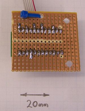
- Start by cutting a 40mm x 45mm rectangular piece of 2.54mm-pitch stripboard. Drill two 4mm holes 30mm apart at one end as shown, and two 3mm holes near one edge 12 mm apart again as shown (with the blue cable tie). Cut all the tracks down the middle as in the photograph, and the 5th track in on the 4mm hole end, also as shown (these last are to prevent the 4mm nuts shorting out the FT232RL UM232R). Solder the FT232RL UM232R to the stripboard, with its USB 'B' connector at the end with the 4mm holes. The end of the connector should be just flush with the edge of the stripboard.
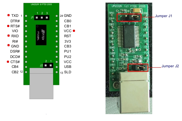
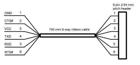
- Cut an 700 mm length of 6-way ribbon cable, split off the six wires at one end to a length of about 25mm, bare them, and tin them. Solder the wires in the sequence shown on the diagram of the wire. The connections correspond to the red dots on the left view. Use a thin cable tie to attach the ribbon cable to the stripboard via the smaller holes. Leave a small loop free to give strain relief. Jumper J1 should connect pins 1 and 2, and jumper J2 should be present. (The picture shows J1 connecting pins 2 and 3, but that's just the default picture from the datasheet - connect pins 1 and 2).
- Attach a 6-way 2.54mm-pitch header to the other end of the cable. Colour the RTS end of the header green with a felt-tipped pen, and the GND end black.


Alternatively it is possible simply to buy a USB to TTL cable here that will plug right into the Motherboard and give you a USB 'A' connector at the other end. This will simplify your initial wiring up slightly, but it will mean that your Mendel will have a trailing lead. If you put a USB socket in the machine and wire it up as above, you will be able to unplug your machine completely and carry it around easily. You will be surprised how useful and convenient it is to be able to do that...
Back to Electronic_wiring.