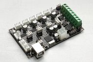
Minitronics 10
Release status: Working
| Description | Single board, plug and play solution
|
| License | |
| Author | |
| Contributors | |
| Based-on | |
| Categories | |
| CAD Models | |
| External Link |
Contents
Summary
File:Minitronicsv1 connectors.png
Configuring Arduino
For Arduino you need to make some changes, best is to download a pre-configured Arduino version from the Reprapworld.com's website. But if you need to adjust your own copy, or adjust a newer Arduino version, you can follow these steps:
- Download the Arduino addons file from the files section below and extract the file.
- Copy the contents in the mega1281.name=Minitronics section of boards.txt to the boards.txt of the Arduino copy (arduino/hardware/arduino/boards.txt).
- Copy the contents of the directories bootloaders and variants to the corresponding directories in arduino/hardware/arduino/.
- Copy Arduino.h to hardware/arduino/cores/arduino
If you start Arduino, you should see Minitronics available as option in the boards submenu.
Configuring Marlin
For Marlin you need an adjusted fastio.h. You can download it from the files section below, place it in the Marlin directory next to Marlin.h. Or you can download a pre-configured Marlin version from the Reprapworld.com's website.
Testing the board
To test the functionality of the board, a test firmware is available. You can download it from the files section. This firmware will help you test the board. Disconnect everything except the USB cable to your computer. Upload the the test firmware to the board with Arduino, the blue debug LED should blink every second. By using the serial monitor in Arduino the board will provide an output like: T1 1023 T2 1023 These values represent the resistance measured from t1 and t2. When you connect a thermistor to the pins, the corresponding value in the serial monitor should change to about 890.
By connecting the 12V line, the MOSFETs should have power and their LEDs will blink in order. This verifies the MOSFETs and 12V power are OK.
Also the stepper motors should turn when connected, with the 12V line in place. They will turn a short time and switch direction.
These three tests will verify the basic functionality of the board.
Basic setup
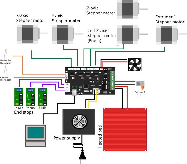
This paragraph will show you how to connect the board. This is just a basic example, your requirements may differ. There is a lot of community support available in the RepRap forums. By placing your questions there other users may benefit of the information too.
First connect your computer with a standard USB cable. The power LED should light up and the blue debug LED should blink once. The rxd and txd LEDs near the USB connector may blink fast for a short period.
Connect the fan to the fan connector on the Minitronics board. The red wire should co on the + side. Place the fan on the bottom of the board with about 1cm distance, so it can cool the board properly. Failing to cool the board sufficiently will result in shutting down of the stepper drivers, which will be bad for your print.
The power supply should be connected to the atx connector using the provided atx wire. Mind the polarization, the yellow wires should be +! Connect the heated bed to LHB, this terminal allows larger currents, up to 10A. The first extruder heater should be connected to LEX1. A cooling fan can be connected to the the LEX1 terminals.
Dual extruder setup
With the dual extruder setup you cannot use the heated bed, because there are only 2 thermistor connectors available. Also an external stepper driver board is required, which can be connected to the EXTSTEP connector. Refer to the datasheet for the pin layout/
Setup for dual extruder is basically the same as with one extruder, only the heated bed thermistor connector will be used for the second extruder. Also the external stepper driver board needs to be connected to the EXTSTEP connector.

