Old RepRap project FAQ
-- Main.ForrestHiggs - 26 Jan 2006
This page has lots of useful information, but also has parts that only apply to Darwin and so are no longer relevant to Mendel and later RepRap designs. If this is your first time here, you probably want the current General FAQ instead.
Contents
FAQ
Index
- Calibration
- Controllers
- Coordinate Systems
- Design Rules
- Extruder Head Mk 2
- Fill Routines
- Hans Warger's Reprap Design
- Building an affordable power supply
- Producing PLA from Indian corn
- Token Ring
- CalibrationHead
Calibration
[Higgs] Question: I've read through the postings and the wiki and it seems to be that we're looking at a .5 mm accuracy for reprap. To that end I've seen a lot said about selecting thread pitches and stepper steps to get that to happen. I've probably missed the rest that got said about this issue but with what I have read it seems to me that we may have a soft place in our development programme at this point.
Looking at the pic in Vik's "Screw-driven axis posting on 17 December I couldn't help noting that in the lateral direction that Vik is depending on the rigidity of those steel rods and the accuracy of the pitch of the threads on that drive rod. It struck me how simple it would be to not get the two ends of the assembly exactly flat and to get just a little torque into the overall track and platform. That small distortion would introduce errors in the whole system. Similarly, if we don't work on an accurately flat working surface we have similar problems.
Introducing rigid non-polymer materials into the design such as Vik's steel rods and keeping the dimensions of the reprap small will, of course, reduce errors. What happens, however, when we try to make more and more of the reprap out of polymer? We'll start getting a system that expands and contracts substantially with themperature. We'll also start getting creep and most of all we'll start getting load deflections magnitudes greater than what we would see if we were using, say, steel.
I'm not trying to say that we ought to think about doing reprap in metal. More what I am doing is wondering how we calibrate a polymer reprap and how we keep it calibrated so that we can assure the desired level of quality control out of the objects that we create.
[Bowyer] Answer: This is something we've thought about, and should perhaps have documented more. Ed and I are using ground steel cylindrical rods 8mm in diameter for this sort of thing which are cheap accurate and strong.
However I agree that the more polymer gets into the RepRap machine the more difficult this sort of thing gets to control. Non-linearities can be allowed for by doing a detailed callibration and making a map, but add dimensions of temperature and RH to that and it starts to get a bit dodgy. Indeed it would probably be easier to run the whole thing in a big cardboard box with a small air-conditioner attached, which I would like to avoid...
The target accuracy is 0.1mm, incidentally. One of the nice things about FDM is that you can build things much more accurately than the thickness of the filament if you allow offsets, in just the same way that (in reverse) you can machine much more accurately then the diameter of a milling cutter.
- ControllersHead
Controllers
[Bowyer] One of the provisional decisions we made a while ago was to have Distributed control - each component of the RepRap machine will have its own microcontroller to make it semi-autonomous; they'll all talk using Simon's token ring or I2C.
The idea is to make the machine as modular as possible so that people can easily add their own new write heads or whatever without changing the rest of the design.
As we progress it's becoming clear that almost all the microcontrollers will be pretty similar - a PIC controlling some H-bridges and power-transistor switches with a few analogue and/or digital inputs. I now have a hope that we will be able to design a universal PCB for these that you partly populate for each device (the XYZ controller will need 6 H-bridges, for example, whereas the extrude head only uses one). I was thinking of making a PCB with the PIC at the left-hand end and a repeated series of drivers to the right, so when you expose the board to the UV light you just put a folded bit of black card over and under at the right hand end to mask off the parts you don't need. It shouldn't be too hard to design the tracks so that works.
Ultimately the RepRap machine will be making its own circuits, of course, and all such messing about will go away.
At the moment the development cycle seems quite fast too - just edit a C program, compile it, and download it into the PIC. I don't use an ICE; just a scope and a lot of debug information reporting in the C code. It normally takes me about two days from picking up a soldering iron to get to a working device, after which I draw out the circuit diagram, add comments to the code, and write the document...
I agree that a more powerful board would possibly allow the elimination of the PC from the system, but users are going to need web access to download designs, and some quite heavy disc space to store lots of them anyway; I suspect a PC will be needed for that, so we might as well use it and bask in the excess computing power and speed it offers us above our needs...
- BuildingJDM
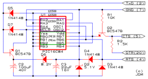
Building the JDM Programmer board for the PIC16F628 chip
Parts List
- R1 10K Resistor
- R2 1.5K Resistor
- D2 5.1V/0.5W Zener Diode (sizing on this part critical)
- D3 1N4148 or 1N4448 Diode
- D4 1N4148 or 1N4448 Diode
- D5 1N4148 or 1N4448 Diode
- D6 8.2V/0.5W Zener Diode (sizing on this part critical)
- D7 1N4148 or 1N4448 Diode
- C2 100�F/25V Capacitor electrolytic
- C3 22�F/16V {Capacitor electrolytic} or 47�F/6.3V Capacitor tantalum
- Q1 BC547B Transistor NPN
- Q2 BC547B Transistor NPN
- P1 DS25 (female) 25 pin DSUB {Cannon} connector
- P2 Connector for In Circuit Programming {omit}
The Transistor
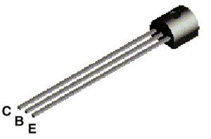
Transistors that we will use in projects look like this:
The transistor has three legs, the Collector (C), Base (B), and Emitter (E). Sometimes they are labeled on the flat side of the transistor. Transistors always have one round side and one flat side. If the round side is facing you, the Collector leg is on the left, the Base leg is in the middle, and the Emitter leg is on the right.
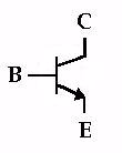
The following symbol is used in circuit drawings (schematics) to represent a transistor.
The Diode
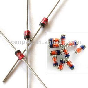
Diodes that we will use in projects look like this:
Diodes have a dark mark on the cathode end. Here we can see the schematic for a diode and laid side by side with a drawing of a diode. Unlike resistors, diodes' orientation is critical to your circuit working properly.
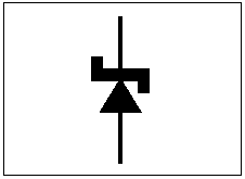
The zener diode is very similar to an ordinary diode. Specifying zener diodes tends to be more critical than what one encounters with specifying ordinary diodes. The schematic representation of the zener diode is very similar to that of an ordinary diode.
The Capacitor
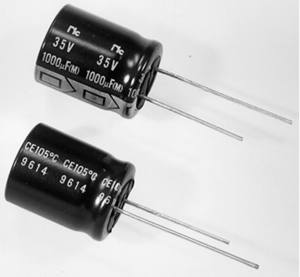
This board uses electrolytic capacitors. Like diodes, electrolytic capacitors are directional and will not work if put in backwards. The schematic for the electrolytic capacitor is seen...
Electrolytic capacitors look like a tiny aluminum can with two leads. They come with one lead shorter than the other. The cathode lead (-) is always shorter than anode lead (+). If you are using a salvaged electrolytic capacitor you can locate the cathode lead by noting the lead nearest a lighter coloured band (called the cathode polarity band) running down one side of the capacitor can. The lead nearest to that band is the cathode lead (-).
Capacitor Working Voltage
One very important rating of capacitors is "working voltage" (WVDC). This is the maximum voltage at which the capacitor operates without leaking excessively or arcing through. This working voltage is expressed in terms of DC but the AC equivalent is about only one half of that DC rating. It is important to note that electrolytic capacitors are not used in AC applications.
[Higgs] Question: you've mentioned that I need to get a PIC programmer. Can you make some suggestions as to what kinds are good ones and who might be decent vendors?
[McAuliffe] Answer: My recommendation for a Windows user would be a JDM programmer and using IC-Prog as the programming software. I think for linux, there are recommendations on the wiki already.
The JDM programmer is probably the simplest design of the many I have seen and it was my second programmer. The first was one I bought many years ago from Microchip at significant expense, but the JDM actually works better for modern devices and it only costs a few dollars in parts. Sadly it does mean a little bit of work to make it. The approach they describe on the web site is a little fiddly just because there are so many wires to connect (they don't use a PCB or even stripboard). It works just fine though because I made mine as described, but it may be easier to make it a different way (just follow their schematic).
IC-Prog is very good and very simple. It's also very free.
JDM programmer: http://www.jdm.homepage.dk/newpic.htm
PIC16F628
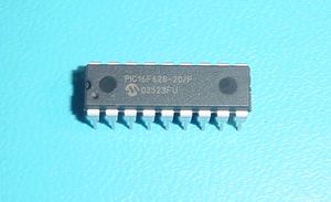
[Higgs] Question: I am assuming that the 16F628 fits into that 18 pin fitting shown on the picture and schematic. The link doesn't talk about the 16F628 being programmed by this board. Could you clear this bit up a little?
[McAuliffe] Answer: Microchip have a whole bunch of chips (probably around a hundred) which is why they aren't all mentioned on that page. The chip they refer to is the PIC16C84 which is pin compatible with the 16F628 (the red outline). The 16C84 is one of the classic and most popular PIC microcontrollers. More recently the 16F628 is taking over much of that popularity. The programmer will program almost all of the PICs, even larger ones if you make a socket adapter.
[Higgs] Question: I've noticed that Simon always refers to the PIC16F628 while Adrian refers to the PIC16F628/P. Are we talking about the same thing here?
[McAuliffe] Answer:
P = PDIP (plastic DIP package) Alternatives are SO and SS for surface mount varieties. You definitely want the PDIP or it won't go into 2.54mm parallel pins.
F = Flash (ie re-programmable in just software). Other devices are either write-once ("C"?) or UV erasable (identified by "JW" though I'm not sure you can get the 628 in that type).
L = low power etc
The full list of these codes should be in the datasheets.
The 16F628A is just the newer model of the processor and is compatible with the 16F628. I don't think they even produce the old model any more but people still just about about the 16F628.
I'm lazy so I just write 16F628 in the generic sense, with the package and speed implied. The full specification of the part you want is probably PIC16F628A-04/P.
[Higgs] Question: When I go shopping for this chip I keep running into the PIC16F628A-I/P and the PIC16F628 20/P which costs about a dollar more and appears to be running at 20 MHz.
[McAuliffe] Answer: Oh, the "I" version is industrial temperature range, which is -40C to 85C. There is also an E package which is extended temperature range, -40C to 125C.
Just go with the PIC16F628A-04/P. It should probably be one of the cheapest and will do exactly what you want.
Cannon connector
[Higgs] Question: When I looked at the parts list for the programmer board I noticed that they specified a 25 pin FEMALE cannon connector. What is with that? The serial connector on the back of my PC is a female connector. Am I not supposed to plug this thing into my pc? Is there an intermediate cable that they're not mentioning that goes between my pc and the PIC programmer?
[McAuliffe] Answer: A female connector is just the convention for "DCE" devices (ie the other end from the computer). If you look at a modem or some other device with a 25 pin port, it should be the same. They are expecting you to put a standard serial cable between your computer and the programmer, rather than plug it directly into your PC. You could probably plug it directly into the PC I suppose, but it's quite convenient to have the programmer sitting on a desk where you can get to it more easily.
Capacitors
[Higgs] Question: C2 and C3 are giving me small fits. C2 specifies a 100 microF/16v electrolytic. The naming conventions here seem to be a little different. I was able to come up with a 100 microF electrolytic rated at 50WVDC max. WVDC meaning working voltage DC and I am not sure whether it I am not sure if it the same thing as simple V.
The 22 microF/16 was even more of a problem. I wasn't sure whether the 22 could be an electrolytic (I got one rated at 35WVDC) or whether, like the 47 MicroF/6.3V, it also had to be tantalium.
Are these two likely to work?
[Bowyer] Answer: Tantalum capacitors are a special kind of electrolytic that are very temperature stable and have better frequency characteristics. An ordinary electrolytic has two plates with an electrolyte in between.
Polarising them the right way causes a film of insulating oxide (or similar insoluble ionic compound) to form on one plate. This is the insulating gap in the capacitor and - because it stops forming when the current stops - it's very thin, so the capacitance is correspondingly high. Tantalum ones work in more or less the same way, except the physics of how they form makes lots of fine cracks, which give a large area for the thin insulator. Neither kind like being polarised the wrong way round - it kills the insulating film.
The voltage ratings are caused by the thinness of the insulating layer: it won't stand a big potential gradient, and - because it's so thin - you only need a few volts to get a massive figure for V/m. My rule of thumb is to go for a voltage at least 1.5 times the maximum that they will experience in circuit. "Working voltage" and "voltage" are the same thing in this context, I think. Putting a capacitor in with too big a value for voltage costs nothing but space - everything should still work.
I just found this, which is good:
http://www.uoguelph.ca/~antoon/gadgets/caps/caps.html
TOOLING UP TO BUILD THE CONTROLLER BOARDS
[Higgs] Question: ...can you suggest what sorts of things I need to use {fabricate} this system {PIC controller strategy}? I can already see that I need to buy a...
IC chip grabber
solder sucker
soldering iron work station
electric fan (so that my eyes don't swell from the flux fumes)
What about test equipment?
Power supplies?
[McAuliffe] Answer: I would say the only thing you really need is a soldering iron and the rest are luxuries, but they certainly wouldn't hurt.
IC grabber: I do use one of these, but a small screwdriver works just about as well (though a lot slower).
Solder sucker: I doubt you'll actually need one
Work station: I wouldn't bother if this is the only thing you plan to make.
Fan: I just blow very gently while I solder and I never get it in my Eyes. :)
For test equipment I use an oscilloscope and multimeter, but the scope is only really useful for development. For building the modules, you really just need an ohmeter or continuity checker to check there are no fabrication errors, so pretty much any multimeter will do. If there are any problems, a voltmeter would be useful to track them down, so a multimeter is enough.
You need a fairly beefy 12V power supply. The exact current isn't yet known of course, but it'll be at least a bunch of amperes. I'm actually just using an old PC power supply. I just bought a PC internal power plug and wired it to a conventional DC power plug so it is the same as a 12V "brick" power supply and just plugs into the DC socket on the rep[st]rap. That gives you a convenient power switch too, which I otherwise don't have right now.
You will also need some miscellaneous bits such as
- Electric drill and suitable size bit for cutting board tracks - Small pliers - Ideally some wire end-cutters, or small snips - A wire stripper - Solder - Something to clean muck off soldering iron (a cotton based cloth is fine) - Connecting wire. I'd suggest two different sizes for low current signals and motor drive lines. - Ribbon wire if available, for cables that interconnect the modules
Probably other things I've forgotten :)
I think we need to start a "HOWTO" page on the wiki at some stage. I may start that quite soon to help with the fabrication and interconnection steps you'll need. Maybe you could help fill it in too by noting down what you do as you build it (it's always harder after the fact).
- CoordinateSystems
Coordinate Systems
[Olliver] Question: What directions are our X,Y,Z axes? Same as AoI?
[Bowyer] Answer: I think we need a RH coordinate system (thumb = X, index = Y, 2nd = Z) and it would seem reasonable for Z to be the vertical/layer direction. But of courseany convention will do.
One thing that is really useful in the Stratasys software is that you can tumble your object about at the last minute to get the orientation right for manufacture, an idea we should emulate, I think. It allows you to point at a face with the mouse and say "make that +Y" o.w.e.; looking at Java3D thatshould be simple to implement - it has a ray-trace query.
- DesignRules
Design Rules
[Olliver] Question: Should I design the stage to fit in place of the top spider, or to fit on it?
[Bowyer] Answer: I think so - when this sort of decision comes up I have a sort of priority list that goes... Make it...
- 1. with RP wherever possible.
- 2. as modular as possible.
- 3. as simple as possible.
- 4. as easy to repair as possible.
- 5. as reliable as possible.
- 6. as strong as possible.
- 7. as accurate as possible.
Conventional engineering would doubtless put 5 and 7 much higher up the list.
But conventional engineering doesn't have self-repair as implicit, nor Darwin to assist...
I'd welcome others' thoughts on different orderings of that list, or on additions and subtractions to/from it.
- ExtruderHeadMk2
Extruder Head Mk 2
[Higgs] Question: Is there some reason besides thermally isolating the brass extruder barrel from the rest of the extruder that we're using PTFE? Is the low friction coefficient of the PTFE critical to Mk 2's operation?
[Bowyer] Answer: No - I don't think so. The PTFE is there as it resists high temperature.
- FillRoutines
Fill Routines
[McAuliffe] Question: The best way to go seems to be to run once round the perimiter, and then to fill the interior at 45 degrees; next level up you do the same but at -45 degrees. I have a little Java program to do this for one of my polygons; it includes offsets, so you can allow for the width of the deposited stream. I am in a bit of a quandry over this, as I haven't started on Java3D yet which may eliminate much of what I've done. But if anyone wants copies let me know.
[Bowyer] Answer: That sounds like a good approach.
I'd be interested in a copy of that rectangle code. I'm going to work a bresenham function into the PIC synchronisation model I've been building so that it should be able to accurately produce a line co-operatively beetween otherwise independent axis controllers. The synchronisation is based on an extra clock/sync line between the co-operating devices and is very simple (along the lines we previously discussed).
That synchronisation is proceeding well, and once it goes I'd like to add a little functionality to the stepper test app for printing lines, rectangles and blocks. So I'll start by using your bresenham implementation, and it would be nice to have your block drawing code thrown in there too. The bresenham will probably only work in two dimensions. I assume it is a lot less useful in the third dimension.
As you say, it might be partly throw-away code, but it's going to be useful for testing (and playing).
I have a little trouble and strife that is dragging me away (as you get around this time of year) so this won't be finished as soon as I'd like, but it's hopefully not too far away.
By the way, I'm currently using a dummy device to simulate plastic extrusion. It currently only does "start extruding" and "stop extruding", indicated by an LED. But this seems overly simplistic to me. What are the likely capabilities required by an extrusion head?
For example, it may be something like:
- Extrude at speed n
- Stop extrusion (possibly different from speed 0)
- Select material n
- Set temperature for material n (0 to turn off heater)
- Wait for current material to reach temperature
- Get current material extruder temperature
- Get quantity of material remaining (maybe just 0 or 1)
- Notify address x when material is low
Does that seem about right? Any others or alternatives?
Perhaps there would be multiple devices. An independent temperature sensor, etc?
Perhaps there is no need to select a material. Each extruder could be independent and you could just print parts by extruding from the appropriate head (taking into account it's position offset). On the other hand if it turns out to be a carousel scheme (picking up a head, like some plotters and automated milling machines do) then we might need to select the material. The carousel scheme does have the advantage that you can support a greater range of materials without requiring a stronger mechanism or lots of space, but it's also more complicated.
With a carousel, perhaps there should be a separate device for controlling the carousel as well, so the extruder API might be simpler or different.
For example, with mechanics to release the head as soon as it reaches the carousel and lock as it pulls away, it could change heads by just moving to the right co-ordinate, then the API could be just:
Extruder:
- Extrude at speed n
- Stop extrusion
- Set temperature, notify address x when reached
- Get temperature
- Notify address x when material is low
Carousel:
Select material n
Or perhaps this could just be a generic motor controller.
Then again, perhaps carousels are best left to Darwin if it's going to add more initial work.
For my repstrap contraption, I'll hopefully get away with just a single head so it's not important but it'd be nice to get something more or less along the right lines committed to code.
- HansWargers
Hans Warger's Reprap Design
[Higgs] Question: I ran across Hans Wargers' turntable design in the Wiki.
http://staff.bath.ac.uk/ensab/replicator/Downloads/Wargers/wargers.html
Did anything come of this design? It looks easy enough to fabricate.*
[Bowyer] Answer: We haven't done anything with it; I don't know if Hans has.
- BuildingPowerSupplies
Building an affordable power supply
See PCPowerSupply.
- ProducingPLA
Producing PLA from Indian corn
[Olliver]
Getting the hulls off of the kernels...
The Germans have a cunning plan:
1. Pressure-cook the kernels briefly, and drain while pressurised.
2. Release pressure suddenly.
3. Let pulp dry under its own heat.
Works with potatoes too.
[Olliver]
A cookbook for making PLA and other "green" polymers.
http://www.chemsoc.org/networks/learnnet/green/docs/plastics.pdf
- TokenRing
Token Ring
http://en.wikipedia.org/wiki/Token_Ring
- DepositionSpeed
What Is The Deposition Rate?
[Higgs] Question: The Mk 2 puts out about 2.83 cm^2 of polymer/hour. How much would you say the Stratasys could extrude?
[Sells] Answer: We're looking at approx 10 cm^3 of polymer/hour for the Stratasys. Which considering they're on Mk 'a-lot', seems pretty achievable I reckon, especially with your NEMA 17's in the ball park.
