Open hardware fast high resolution LASER
The goal of this article is to describe a transparent polygon laser diode scanner. The article aims to block further patent claims and make room for an open-hardware version.
Contents
Description
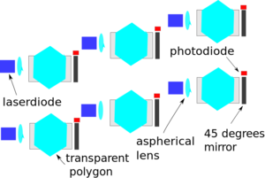
Commercial laser diode sources can provide light at wavelengths down to 375 nm. The maximum power for single mode commercial laser diodes of 405 nm and 375 nm is 350 mW (SLD3237VF) and 70 mW (NDU4116) respectively. The SLD3237VF is used in a 4x blue ray writer. Blue ray writers with 16x use stronger laser diodes, but no official data sheets are known (1 watt is typically claimed). At short wavelengths, laser diodes cannot give enough power to solidify large substrates fast. This is critical for a high waver througput in printed circuit board manufacturing. Also for large area ceramic photo-polymerization printers, a lot of energy is needed. The critical energy dosage for 60% volume percent silicon oxide and 55 volume percent alumina is 60-400 mJ/cm2 and 500-3300mJ/cm2 respectively [source: Critical Energy for photo-polymerization of ceramic suspension in acrylate monomers, John W. Halloran]. As a result, it can be advantageous to combine several laser diodes need to solidify a single layer. This article provides a particular solution for this problem. Light can have up to two polarizations, as a result up to two single mode laser diodes can be combined into one bundle. A beam splitter cube is typically used to combine the laser diode bundles. In the figures shown to outline the solution, a single laser diode is focused directly via an aspherical lens. This results into an elliptical spot. A spherical spot can be achieved by first collimating the laser diode with an aspherical lens and then circularizing the bundle with an anamorphic prism pair. The bundle can hereafter be focused with for example an achromatic doublet. The polygon can be made by polishing the sides of a quartz sheet. Key is to realize that in reflective polygon scanners it is advantageous to hit the bundle with a large collimated spot. In transparent polygon scanners, the beam is focused and the spot can be smaller; which keeps the disk light. The bearing of the scanner can be created via a ball bearing, an air bearing or a self-sustaining air bearing. After focusing, the laser diode bundle is displaced by rotating a transparent plate. The transparent plate is formed by the opposite sides of a regular convex polygon with an even number of sides. The illumination head is moved perpendicular to the scanning direction. As a result, the substrate can be solidified. Another solution would be to move the substrate relative to the now static illumination head. This could be desirable as self-sustaining air bearings with a high speed rotating disk are best kept in a static position. In figure 1 A, a possible embodiment is shown.
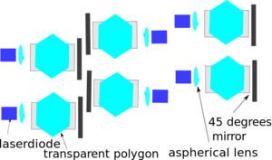
Another embodiment, where one of the polygons in a subunit is rotated is shown in figure 1B.
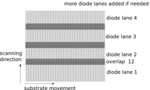
Other embodiments are also possible, key is that the laser diodes can illuminate lanes which overlap partially, if the illumination unit or substrate is moved orthogonal to the illumination direction on the substrate. Both embodiments can be used to solidify six lanes. These lanes partially overlap, to allow for correction of the laser diode spot alignment errors. Four lanes and three overlaps are shown in figure 1C.
The alignment errors can be detected by a camera which is moved under the illumination unit in the setup. Projection should be done directly on the CCD chip of the camera. A gray filter can be placed on the camera to protect the CCD chip. A camera lens should not be used. The errors can then be corrected for in a slicer based on, for example, the Visualization ToolKit and a spot detection module based on OpenCV. Naturally, these libraries come with a convenient Python library.
Search Report
There are several other laser diode polygon scanners which can be used to combine the power of multiple laser diodes. KLEO Halbleitertechnik which was partly owned by Zeiss and later sold to Manz sells the speedlight 2D. The Speedlight 2D is a system which uses 9 polygons and 298 laser diodes to solidify a substrate with a width of 600 mm. The reflective polygon has 32 facets and rotates at a speed of 50.000 rotations per minute, see patent US8314921B2. The Netherlands Organization for Applied Scientific Research (TNO) has done a lot of research in transparent polygon scanners. It developed a system which is similar to that of Kleo AG but uses a transparent instead of a reflective polygon, for details see patent application WO 2015/160252 A1. The transparent polygon scanner proposed in this article is different than that from TNO in that it uses a single and not multiple optical bundles per transparent polygon. In addition, the rotation axes of the the proposed system are orthogonal and not co-planar with the substrate. As said, the single optical bundle can be made with up to two laser diodes. It might be beneficial, to use laser diodes with larger wavelengths. These wavelengths could be used to sinter powders or metals. Another possibility would be to solidify egg whites with infrared radiation in a food printer. Explosives, piezoceramic materials and metals can also be fabricated via photo-polymerization.
Business case
Competitor Analysis
High end large-photo polymerization machines or PCB machines tend to be closed source and start at 250K euro’s. For the business case, the following machines have been taken into account. In the photo-polymerization market competing machines are the PromakerL7000D (Prodways), ProX 950 (3D Systems) and XEDE 3SP(Envisiontec). Formlabs has been omitted as it uses a colimated bundle, i.e. the laser diode is not focused. The number of pixels offered by DMD printers like the Rapidshape or Carbon 3D is seen to be too small even with a 4K DMD. In the PCB market competing machines are the Nuvogo Fine 10 (Orbotech), Speedlight 2D (Manz) and the Ledia 3WL (Ucamco).
Competing Technologies
The following technologies can be distinguished;
- Polygon scanner with f-theta lens and one laser bundle
- Used by: Envisiontec uses up to two 405 nm laserdiodes, Orbotech uses a Paladin laser
- Limits: Three element f-theta lenses are expensive, telecentric systems are even more expensive and cannot project outside the lens .
- Reflective polygon scanner with multiple laser bundles
- Used by: Manz
- Limits: the polygon tilt angle is smaller than 45 degrees, still expensive
- Transparent polygon scanner with multiple laser bundles
- Used by: LDI Systems (defunct)
- Advantages: telecentric projection, system can project outside the lens, as a result polygon tilt angle can be 45 degrees
- Limits: at best proof of concept, expensive to build
- DMD chip illuminated with LEDs
- Used by: Ucamco and Prodways
- Advantages: Chips can be illuminated with multiple wavelengths which can be advantageous for PCB manufacturing
- Limits: multiple beamers can be placed adjacent to each other but this expensive, as a result Prodways translates the beamer and illuminates a 45 degrees mirror, if the mirror is illuminated with laserdiodes this can result into multiple-slit interference.
- Galvo scanner with Yagda laser
- Used by: 3D Systems, Materialize
- Limits: low power and frequency of yagda laser, due to inertia galvo scanners are slow than polygon scanners
In the PCB market only Kleo uses laser diodes at 405 nm. The system should be designed such that it is a lot cheaper. For the business case it can be assumed that the Speedlight 2D costs approximately 1 million euro's. Technologies like the grating light valve, sold by silicon light machines, is typically used for PCB with features below a 1 micrometer. Too few applications of the MEMS scanner developed by Fraunhofer were known to take it into consideration.
Competing Light Sources
The following light sources have been considered;
- Light Emitting Diode (LED)
- Price: 5 euro's per LED
- Wavelengths: 405, 395, 385, 374, 365
- Frequency: set by other element in the optical path, e.g. the refresh rate of the DMD chip
- Note: LEDs offer less contrast and depth of field than laser diodes but can easily be combined as they do not interfere. Texas instrument has a monopoly on DMD chips. Projection systems are sold by other vendors; for example, the LUXBEAM Lithography System sold by visitech for >10k euro's. DMD chips do not handle short wavelength easily. For wavelengths below 405 nm, the power limit is currently 4 watts per chip DLP9000UV.
- Laser Diode (LD)
- Wavelengths: 405, 395, 375 nm
- Frequency: 50 MHZ
- Price: 40 euro's at 405 nm, 1000 euro's at 375 nm
- Power: 0.4 watt at 405 nm, 70 mW at 375 nm
- Cooling: most laser diodes do not operate well at temperatures above 30 degrees, but some can handle 80 degrees.
- Used by: Kleo, Envisiontec
- Diode pumped solid state laser
- Vendor: Coherent
- Power: 24 watt
- Wavelength: 355 nm
- Price: 177k euro's (only laser, you also need a chiller and a power supply)
- Sizes: LASER 305 x 200 x 1100 mm, power supply 482 x 177 x 505 mm,
- Frequency: 80 MHZ
- Solid state laser ND: YVO4
- Wavelength: 355 nm
- Power: 1 watt
- Frequency: < 1MHZ
- Used by: 3D systems and Materialise
Proof of Concept
To understand the business case, please use the above to realize that competing systems are expensive and that not a lot of systems use laser diodes. For a viable business case, the price per transparent polygon and laser diode is key. As a result, only a single transparent polygon scanner has to be built. Firstly, it has to be shown that a single quartz sheet can be rotated at high speeds at low costs. For the proof of concept, the Ricoh Aficio AF-1027/270 can be used. The reflective polygon can be removed from the polygon and after flattening a transparent quartz sheet can be placed on top. This quartz sheet should weigh less than 8 grams. Key is to check whether the transparent sheet can rotate stable at high speeds, e.g. 20.000 rotations per minute. If this has been shown, the price per polygon is known and the price per diode and throughput can be calculated. At the moment, the price per transparent polygon unit is thought to be 300. (edge polished quartz sheets are not readily available and in the order of 150 dollars). The price for a light engine with 80 diodes would be something like 24K euro's. If the rest of the machine costs 30K euro's, the total price is estimated at 54K euro's . With a 70 percent margin it could be sold at 180K euro's, which would allow it to compete with commercial machines in the proposed business segment in the 3D printing with a 50 micrometers spot size. For the PCB market, the resolution target is 10 micrometers. This market is best targeted after 3D printing. From an investment point of view, the technology can be interesting as it can be funded in multiple rounds. The transparent polygon is build in the first round. This will be cheap (i.e. 10K) but have a high risk. In the second round, a complete engine can be sponsored (e.g. 50K euro's). Finally, in the third round a proof of concept tool could be built. This would cost something like 100K euro's. Only R&D costs has been accounted for in these investment rounds. The fact that the laser diode spot can be kept into position with a laser diode driver, photo-diode and a field programmable gate array (FGPA) has already been shown in for several reflective polygon scanners. It would, however, be nice to make an open source laser diode driver based on (MyHDL) and for example, the Lattice iCE40, used in project (Icestorm).
Physics
The bundle has to be focused before it impinges on the transparent polygon. If the bundle is focused after the transparent polygon, it will not be displaced if the transparent plate is tilted. A transparent plate will displace the focal point of focused bundle longitudinally in the direction of the laser diode. If the transparent plate is tilted, the spot will be displaced transversely at a non constant velocity. Typically, a polygon scanner has a constant spot speed, this is why f-theta and not telecentric lenses are used in a reflective polygon scanner. The non-constant velocity results in a dosage variation which has to be corrected for by the laser diode driver by changing the pulse frequency or the amplitude of the laser diode bundle. The transparent plate will introduce the following Seidel Aberrations; spherical wavefront aberration, coma and astigmatism. The transparent plate does not introduce Petzval field curvature. The Seidel aberrations of a parallel plate are given by Wyant in a document titled Basic aberrations and optical testing. The Seidel aberrations can be used to calculate the Strehl radius. The maximum tilt angle at which is illuminated must be chosen such that Strehl ratio is larger than a limit acceptable for the application. Typically, the Rayleigh limit is used which correspond to a Strehl ratio of 0.71. The calculation can be verified with an open optical ray tracing and lens design framework, such as the Python library made by Dr. Jordens named Rayopt.


