Opto Isolator v1.0
Contents
Opto Isolator v1.0
Overview
<div class="thumb tright"></div>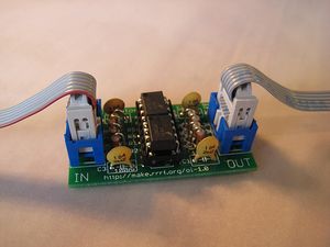
- You'll need a soldering toolkit to do most of this.
- Read our Electronics Fabrication Guide if you're new.
Get It!
Full Kit
Raw Components
Files
<div class="thumb tright"></div>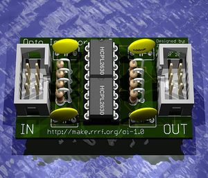
You can download the electronics files from Sourceforge.
This file contains the following:
- GERBER files for getting it manufactured
- PDF files of the schematic, copper layers, and silkscreen
- Eagle source files for modification
- 3D rendered image as well as POVRay scene file
- exerciser code to test your board.
Schematic
<div class="thumb tright"></div>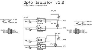
Interface
The opto isolator isolates 2 circuits electronically by sending data as light. It has 2 separate VCC and 2 separate Ground connections.
IN
This is the side that is sending data.
| Pin | Name | Function |
| 1 | IN_VCC | This is the pin to supply +5 volts from the 'local' power supply. |
| 2 | IN1 | This is the signal 1 pin. Connect this to the pin on your uC sending data. |
| 3 | IN2 | This is the signal 2 pin. Ditto. |
| 4 | IN3 | This is the signal 3 pin. Ditto. |
| 5 | IN4 | This is the signal 4 pin. Ditto. |
| 6 | IN_GND | This is the ground pin. Connect it to your 'local' ground.
|
OUT
This is the side that is receiving data.
| Pin | Name | Function |
| 1 | OUT_VCC | This is the pin to supply +5 volts from the 'external' power supply. |
| 2 | OUT1 | This is the signal 1 pin. Connect this to the pin that will be receiving data. |
| 3 | OUT2 | This is the signal 2 pin. Ditto. |
| 4 | OUT3 | This is the signal 3 pin. Ditto. |
| 5 | OUT4 | This is the signal 4 pin. Ditto. |
| 6 | OUT_GND | This is the ground pin. Connect it to your 'external' ground. |
Build It
Board Bugs
- No bugs yet, please report any you find to the forums.
Printed Circuit Board
<div class="thumb tright"></div>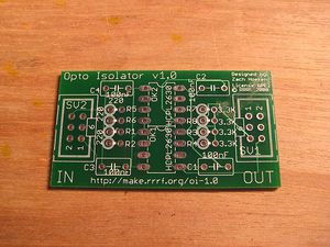
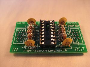
You can either buy this PCB from the RepRap Research Foundation, or you can make your own. The image above shows the professionally manufactured PCB ready for soldering.
Components
<div class="thumb tright"></div>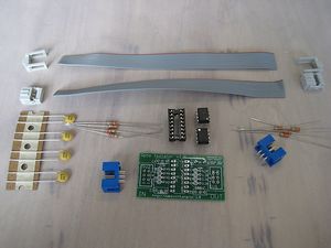
<iframe width='650' height='300' frameborder='0' src='http://spreadsheets.google.com/pub?key=pmEMxYRcQzzATwbOb71BmGA&output=html&gid=39&single=true&widget=true'></iframe>
Soldering Instructions
<div class="thumb tright"></div>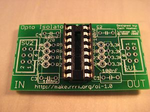
Socket
The socket will hold both chips. Make sure the semi-circle lines up with the mark on the silkscreen.
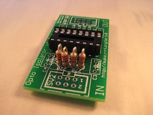
220 Ohm Resistors
Fold the wire over close to the body and insert it into the PCB. Make sure the wire faces the chip socket.
3.3K Ohm Resistors
Fold the wire over close to the body and insert it into the PCB. Make sure the wire faces the chip socket.
C1-C4
Ceramic capacitors can be inserted in any direction.
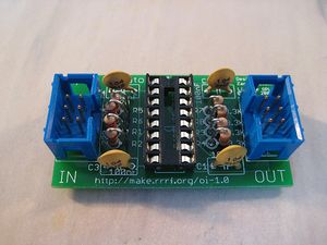
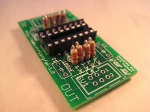
IDC Headers
Insert the headers and solder them. Make sure you put the notches facing inwards so that they line up with the silkscreen.

Insert Chips
There are 2 chips to insert. Insert one at the very top, and one at the very bottom. They both have a semicircle mark that needs to line up with the top of the board and the semicircle in the socket as well as the silkscreen.
Insert IDC Cables
First, you must make some IDC cables. Next, insert them into the headers. They're keyed, so they can only be inserted in one orientation. Yay!