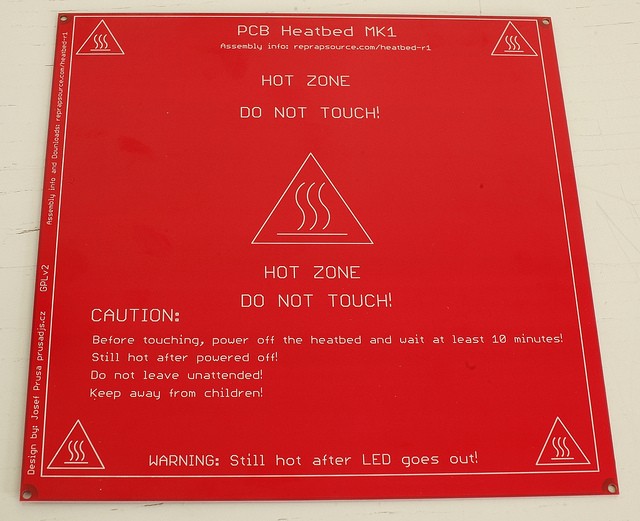
PCB Heatbed
This page is a development stub. Please enhance this page by adding information, cad files, nice big images, and well structured data!
Release status: unknown
| Description | PCB Heatbed
|
| License | unknown
|
| Author | |
| Contributors | |
| Based-on | |
| Categories | addons
|
| CAD Models | |
| External Link |
About
PCB heated bed. I'm working on this idea for nearly six months, inspired by neufeld.newton.ks.us/electronics/?p=864 .
Printing
Cover the bed with kapton tape. Degrease it and print.
ABS temp: 110°C PLA temp: 50-60°C
MAKE SURE YOUR PSU HAS 10 MORE AMPS SPARE!!!
Mounting
Known working solution, I (prusajr) use is Glass sheet (3mm) with glued on cork standoffs and on top of that is glued the heatbed. http://www.flickr.com/photos/prusajr/5410919911/ http://www.flickr.com/photos/prusajr/5410919707/
We are now working on simpler mounting solution!
Sides
PCB Bed has two sides, one with the traces (bottom side) and one with silkscreen (top).
Printing on top side is safer, works great.
Printing on bottom is more effective and heats up quicker.
Connection
Polarity doesnt affect anything.
Leds
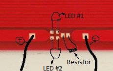
There is place for two leds you should put each of them in different direction so atleast one of them is lighten up, no matter what polarity you use.
RAMPS
There are two way how to power the heatbed. 1) You can omit the fuse on the board and use one of the mosfet outputs. 2) Plug one heatbed wire to the GND pin on the mosfet output on RAMPS and connect the 12V+ separately to your powesupply. (Better)
Its now in working state, Printed load of kits on it, working great.
Main Idea is to use resistance of pcb traces as heating element.


