PCB Heatbed
Release status: working
| Description | PCB Heatbed
|
| License | unknown
|
| Author | |
| Contributors | |
| Based-on | |
| Categories | |
| CAD Models | [[1]]
|
| External Link |
Contents
WARNING
"WARNING!!! Be aware from where you buying the PCB heatbeds!! There is one critical thing, the heatbed must be etched directly from 35um copper clad! ASK YOUR SELLER!!! If the board is plated, as it's normally done, no manufacturer can guarantee the final thickness of copper or even how even the copper is around the board. Which means that the final power wont be evenly distributed around the board or the board wont have high enough output generally.
Main warning sign are plated holes! Plating of holes requires copper plating.
About
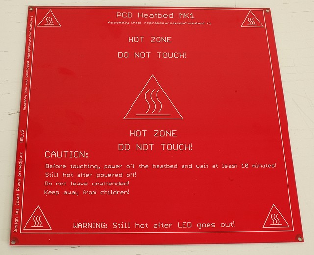
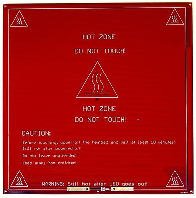
PCB Heatbed MK1 is developed by Josef Průša
- 200 mm x 200 mm active heated area
- 209 mm center-to-center mounting holes (outside the active area).
- 214 mm x 214 mm total PCB size
I was working on this idea for nearly six months, inspired by neufeld.newton.ks.us/electronics/?p=864 .
Where to get it
The .brd file is available here: [[2]]
Mechanical drawings for designing mounting plates/etc (if desired) are here: [[3]]
(Please note that I dont get any provision from these :-)) Manufactured PCBs can be found here:
Asia
Reprapdiscount Hong Kong and Worldwide
EU
GADGETS3D (Poland, Worldwide) http://gadgets3d.com/index.php?route=product/product&product_id=68
RepRapSource (Germany) http://www.reprapsource.com/en/shop/show/6403
eMotion Tech (France) http://www.reprap-france.com/lit-chauffant-et-accessoires/10-pcb-heatbed.html
Cubic Print (Germany) http://www.cubic-print.com/PCB-heated-bed
LHPPortugal(Portugal) http://www.lhpportugal.com/loja/index.php?route=product/product&product_id=193
Paoparts (France) http://www.paoparts.com/fr/200-plaque-chauffante-mk2a.html
USA
Printing
Cover the bed with kapton tape. Degrease it and print.
ABS temp: 110°C PLA temp: 50-60°C
MAKE SURE YOUR PSU HAS 10 MORE AMPS SPARE!!!
Mounting
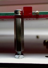
Known working solution, I (prusajr) use is Glass sheet (3mm) with glued on cork standoffs and on top of that is glued the heatbed. http://www.flickr.com/photos/prusajr/5410919911/ http://www.flickr.com/photos/prusajr/5410919707/
When mounted only using the four corners, the inherent warp of the pcb can be a problem, hence it is better to use the cork mounting system above (as the piece of cork in the centre helps to keep the pcb flat).
Magnets can be used in replace of the cork, this makes the bed removable. However, I (mooneyj) have only tried this on a darwin type printer (where the build platform only moves in z). During fast printing, the darwin vibrates and it seems the heatbed magnets slide over each other slightly. The acceleration of the y axis on a mendel may cause the magnets to slide also. Perhaps a hybrid of magnet and bolt mounting would work well?.
The current standard, however, is to simply place the glass on top of the heatbed, and affix it on the four sides with bulldog clips. The clips will not melt under pressure, and sufficiently hold the glass to the bed. This makes removal more easily for cleaning as well.
Note: According to the Eagle file posted on Thingiverse, the M3 holes are spaced 209 mm
Mechanical drawings are here: [[4]]
Sides
PCB Bed has two sides, one with the traces (bottom side) and one with silkscreen (top).
Printing on top side is safer, works great.
Printing on bottom is more effective and heats up quicker. (Though the LED, resistor and wire connections are liable to collision with the print head. Also the tracks could be damaged if the print head collides. Make sure your z-bed-springs are not too strong to prevent damage during a collision).
Connection
Optional LEDs
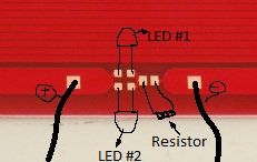
The LEDs are optional, but if you choose to use the LEDs you MUST install the resistor.
'Parts'
2 x Surface Mount LEDs
1 x 1K ohm Surface Mount Resistor
Mount the LEDs in different directions (polarity) so that one of the LEDs will light up regardless of the board's polarity. You can use a single LED if you are certain of the polarity.
Electronics
RAMPS
See RAMPS1.4, RAMPS1.3, or RAMPS1.2 depending on your version.
Sanguinolou The MK2 PCB heatbed heats up to 110C when powered through the heated bed connection on Sanguinolou, your power supply should be 300W and ensure your wires from your power supply to the Sanguinololu should be capable of handling the total draw of 20A+. Using a 300W ATX power supply with the 4wire ATX dual 12V connector is working well for me.
N.B. It is recommended that you use a heatsink on your heated bed mosfet, it will get hot!
N.B. It is recommended that you measure the resistance of your board. I (evilB) didn't and blew up my Ramps 1.2 MOSFET because of a too high current. My measured resistance was 0.8 Ohm.
Testing
Its now in working state, Printed load of kits on it, working great.
Main Idea is to use resistance of pcb traces as heating element.
The following video shows a PCB heatbed MK2 being heated to 60 degrees as seen by an infrared camera: <videoflash>QE90bDUaAno</videoflash>
FORKS (not done by Prusa)
MK2
(It's not successor of MK1 even with it's name. It's concurrent design. - Josef Prusa)
About
MK2 Heatbed - Minor changes by Tony Lock
I liked Josef's original design but wanted to be able to use through hole components, have the thermistor poke through the middle and for it to look good on the 'back' with the silkscreen that Josef designed on that side as well.
The MK2a has a few further changes:
- A mounting hole in the middle of one edge to allow for easier bed leveling
  thanks to Nophead for this suggestion.
- Larger LED and Resistor pads to allow for 1206 size surface mount components
- Much larger area to solder the current carrying wire, easily connect ribbon cable
    (such as with the Mendel90 headbed connection). Also the through holes increased in size.
- The redundant pads on the non-heating element side of the board removed to prevent confusion.
   These are not electrically connected if the board is not plated (plated boards are bad for the
   reasons outlined by Josef Prusa above).
Where to get it
The MK2 .brd file is available here: File:PCB heatedbed Mk2.brd
The MK2a .brd file is available here File:PCB heatedbed Mk2a.brd
Manufactured MK2 PCBs can be found here:
Reprapdiscount MK2 and MK2a eBay
Printing
MK2
Although you can print directly to the bed covered in polyimide tape, no PCB is perfectly flat. It is recommended that you follow the directions in mounting, below, for better results.
Mounting
MK2
The MK2 board can be mounted either side up and is designed to be mounted as Josef describes:
http://josefprusa.cz/pcb-heatbed-final-mounting-and-wiring-solutio
The holes in the 4 corners to attach the heated bed MK2 to the top print plate are not suitable for M3 bolts though! Use M2.5 instead.
The glass protects the tracks from a head crash and is easily swapped out.
The board dimensions are identical to the MK1 design.
Insulation between the board and the thick plate should improve heat-up times and reduce energy consumption. An example is here:
http://reprap.org/wiki/Mendel_heated_bed#Thermal_Insulation
Caution, I have not tried this with the temperatures that the PCB bed can reach!
MK2a
The MK2a has a central mounting hole on the front side to allow for three point mounting. This is much easier for bed leveling in comparison to 4 point mounting. First level the side with two holes and fix in place, then level the side with one hole. A glass plate is highly recommended to provide a truly flat surface and rigidity.
Sides
MK2
The PCB still has a side with the traces on and a side without but now the silkscreen is on both the top and bottom, this makes it look good even when 'upside down' under a layer of glass. The LED, resistor and power wires can be mounted on either side of the board, with either surface mount or through hole components. If you are using through hole be careful when soldering not to interfere with the glass and introduce a gap between the glass and the PCB. If the MK2 board is made properly without copper plating then be sure to only solder the LED and resistor to the same side and the tracks. This problem is solved in the MK2a by removing the pads on the non connected side.
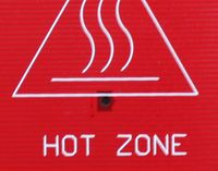
There is a central hole in the board (similar to this one http://wiki.makerbot.com/cchb1). It is sized so a small thermistor (for example the EPCOS one: http://uk.farnell.com/jsp/search/productdetail.jsp?CMP=i-ddd7-00001003&sku=3878697 ) will fit though it allowing contact directly with the glass. todo: test efficacy of using heat sink compound to better thermally couple the thermistor to the glass
Connection
Polarity doesn't affect the PCB, however the LEDs have a polarity.
MK2
There are pads and un-plated through holes for connecting the power wires. Ensure that the wire you use is thick enough for 10A, and solder it to the pads on the track side of the PCB. It is a good idea to think about strain relief so your moving build platform does not flex the joint, this can lead to failure of the joint over time. I recommend routing the wire from the heated bed to strain relief on the thick sheet before routing it to your controller/power supply. todo: get pictures of strain relief
MK2a
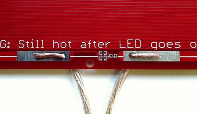
The pads to solder onto have been greatly increased as shown in the picture below. The picture shows the wires prepared for soldering routed through the holes for extra security. This does not remove the need to use proper strain relief.
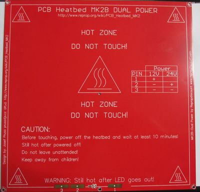
MK2b Dual Power
As you can see in the picture above depending on the voltage you want to use you have to use different solder pads, but it's written on the PCB which pads have to be used for which voltage.
Optional LEDs
MK2
The LEDs are optional, but if you choose to use the LEDs you MUST install the resistor. Solder the components to the pads on the track side of the PCB. With the MK2, conventional wired parts can be substituted for the surface mount parts. If your MK2 board is made properly without copper plating then be sure to only solder the LED and resistor to the same side and the tracks. This problem is solved in the MK2a by removing the pads on the non connected side.
'Parts'
2 x surface mount (0805 size on the MK1 and MK2, 1206 size on the MK2a for easier soldering) or conventional through-hole LEDs. Install with opposite polarity so one or the other will light up regardless of the polarity of the power supply to the board.
1 x 1K ohm surface mount or through-hole resistor
MK2b Dual Power Technical Details
- Dimensions 214mmx 214mm
- Laminate FR4 1.6+-0.15mm
- 2 layer, 35μm copper
- Red Soldermask - both sides
- White Silkscreen - both sides
- Power Input: 12V or 24v
- copper plated holes
- resistance between 1.0 and 1.2 ohm
Very good in combination with RUMBA or Taurino Power
