PCB adaptions for Mendel
Contents
Notice: Optional Improvements
This page includes many suggestions for the RepRap Mendel electronics Mendel Electronic Wiring that are not necessarily required to get your RepRap working. Although less optimal, RepRap Mendels have been built with standard Makerbot gen3 electronics without problem. Thus this page is optional in your gen 3 electronics assembly.
OPTIONS
Before making these modifications to your brand new boards consider the following option. You can leave everything on your boards stock except for adding the I2C pins needed for communicating with the extruder board.


This option will save you a lot of time and reduce the risk of damaging your boards. To eliminate the need for modifying the boards you will need to do three things.
1. Install Molex conectors on your stepper motors (all except the extruder motor). Note that these are different from the molex connectors found on ATX power supplies.


2. Use an ATX power supply
3. Use MakerBot end-stops with RJ45 connectors

These 3 changes are relatively minor compared to the below option, but the choice is yours.
optional changes to convert from Makerbot RJ45 connectors to screw terminal connectors
If you buy ready-assembled printed circuits for RepRap that will save you a lot of time. But the connectors they come with are for the MakerBot CupCake machine, not RepRap. This page tells you how to modify them. You will need a soldering iron, long-nosed pliers, forceps, and a small screwdriver. If you have one, a solder sucker will also be useful.
BOM
Total # of assemblies: 5
| Name | Qty/assembly | Total Qty | Type |
| Stepper Motor Driver v2.3 | 1 | 3 | |
| 5.08mm-pitch 2-pin screw terminal | 1 | 3 | |
| 3.81mm-pitch 4-pin screw terminal | 1 | 3 | |
| 2.54mm-pitch 3-pin polarized header | 1 | 3 | |
| Motherboard v1.2 | 1 | 1 | |
| 78L33 TO-92 3.3V regulator | 1 | 1 | |
| 100uF (107K) Radial-pin Aluminum Electrolytic Capacitor | 1 | 1 | |
| 2.54mm-pitch 2-pin header - 2 pin | 6 | 6 | |
| 2.54mm-pitch 2-pin jumper | 1 | 1 | |
| Extruder Controller v2.2 | 1 | 1 | |
| 2.54mm-pitch 2-pin screw terminal | 1 | 1 | |
| 2.54mm-pitch 2-pin header - 2 pin | 1 | 1 | |
Replacing the connectors on the stepper driver boards
The RJ45 connectors are low-cost, as is the cabling for them. But they are not very neat. To replace them do the following.

Use a pair of forceps to pull the gold-plated connectors inside the RJ45 shell and push them up through the top. Then pull them out from the top and straighten them out.

Next desolder each connection separately, pulling it out with long-nosed pliers. The plastic shell will then be easy to remove.

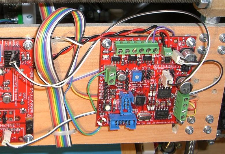
This shows all modified connectors. The original is on the left; the modified is on the right. The two RJ45 connectors have been removed as above. The bottom one at A - the MIN connector - has been replaced by a 3-pin 2.54mm-pitch pin-strip connector. The RJ45 connector just above A - the MAX connector - has also been removed, but Mendel doesn't use this so you can leave it there if you like.
The power connector (at B) has been replaced with a two-way 5.08mm-pitch screw connector. The other two power connections are not needed. This allows the 12 volt power wires to be permanently attached to the board with the screws. The ground connection is on the left in the picture, and the +12v connection is on the right next to the capacitor. Removing the power connector is the only difficult operation that needs to be done on this board. The only way to do it is to clamp the board, put a small screwdriver under the connector at one end, desolder the connection (wait for the solder to melt fully) and lever the connector slightly away from the board. Hold it away while the solder freezes. Then move on to the next connection. By working back and forth between the connections in sequence you will eventually be able to remove the connector. Don't forget allowing the solder to freeze - this puts the next connection along under tension for the next step. Make sure the solder is fully-melted before you start levering, otherwise you may strip the copper from the PCB.
Be sure that when you solder the screw connector onto the board that the solder makes electrical contact with the pin and both pads, on the top and bottom of the board. Failure to do this can result in a board whose power LED does light up, but that is unable to provide power to the motor.
The stepping-motor connector (at C) has been removed and replaced by a 4-way 3.81mm-pitch screw connector. To remove the original connector place the board in a vice, clamping it so that the jaws just cover the letters A B C D on the board's silkscreen. Then desolder each pin separately and pull it out with long-nosed pliers. The plastic spacer will come away with the last pin.
You can just put the motor's wires straight in the screw connector without needing to put a corresponding connector on them. Do tin the ends of the motor's wires first, though.
Replacing the connectors on the Motherboard
First remove the RJ45 connectors at D (below) and to the left (see above in the stepper-motor control board section for how).

Now the tricky bit: removing the chunky power connector at C.
If you do this right, it takes time, but not a toll.
The trick is to remove the pins one by one. Grasp them firmly with forceps, apply a soldering iron to the back (get the right pin...), wait for the solder to melt right through, then pull the pin out.

When you're done solder in the link shown at the penultimate pair of holes on the right, a 3.3 volt regulator (78L33 - get the TO-92 packaged one) and a 100 μF capacitor just to the left of C. The regulator has its flat facing the bottom of the picture. The negative pole of the capacitor faces goes to the bottom of the picture too. The positive pole of the capacitor shares the same hole as the leftmost regulator pin.
Now the easy bits: clip away the chunky 30 ohm resistor at E. Make sure there is at least one connection to SDA and SCL at B (if the standard socket connectors are on the board those are fine). It is also useful to have a ground pin soldered in somewhere on the board. This can either be at B or one of the two pads labeled GND just under the ATmega644P microcontroller chip. Make sure there are two pins and a jumper at A.
Replace the RJ45 connectors you removed with 2.54mm pin headers as shown at D and to its left.

Finally on the back of the board solder a link from the fourth pin of the 6-pin USB<->serial connector to the corner pin of the ICSP connector as shown. This allows the entire board to be powered from the USB cable. Make sure the link doesn't short on any of the other connections. (Unlike me, you may care to put a short length of heat-shrink on it to insulate it...)
Replacing the connectors on the Extruder Controller

Here you just need to replace the RJ45 connector at A. Remove it using the technique in the stepper-motor controller section above, then solder in a 2.54mm screw connector for 12 volt power and a 2.54mm 2-pin header for RS485 comunications as shown. The +12v connection is on the right, ground is on the left.
Mixing RepRap boards with MakerBot boards
If you wish to use some of each kind of board, such as a RepRap or Tech Zone Remix extruder board connected to the MakerBot motherboard, then you will have to break the serial and power connections out from the cat-5 cable. Wires 1 and 2 are the RS-485 serial lines (A and B). Wires 3 through 5 are +12V. Wires 6-8 are GND. Using all 3 power wires allows for more amperage than a single wire is rated for in a cat-5 cable.
Required wiring changes to use the reprap.org firmware
The reprap.org firmware for the gen3 uses a stepper for the extruder instead of the makerbot DC motor. This is more precise, and can be done with only minor wiring changes. This modification uses the dual h-bridges on the stepper extruder, which could normally drive two DC motors, to instead driver a single stepper motor. This has been described as a "nasty hack" and can be a bit touchy to get working correctly. Many people do use it without problems. It may, however, be simpler to buy an additional stepper driver board (be it gen3 type, pololu or whatever) and use that instead.
Hook up the step and direction signal wires
First, look at http://objects.reprap.org/mediawiki/images/4/42/Wiring-diagram.png and notice in particular the wiring of SDA to D10, and SCL to D9. These are used as step and direction signals, and the extruder controller listens to these and controls the stepper (via the h-bridges) accordingly. On the motherboard, SDA is step and SCL is direction. On the extruder controler, D10 is step and D9 is direction.
See http://www.rmorrison.de/RepRap/Mendel_Wiring_MB_Extruder.JPG for a picture of what that looks like.
Tie the grounds of the motherboard and extruder board together
Run an extra wire from the six-pin right angle connector on the left side of the motherboard to the ground on the 12V power connector on the extruder controller. Look for the heavy black line in this picture: http://i.imgur.com/QDQyB.png
This isn't always needed, but it often is. The RS485 connection between the motherboard and extruder controller is immune to differences in the voltage level of "ground" and it's not uncommon for there to be several volts difference between the ground on one board and the ground on the other. Tying them together will solve that problem, and allow the step and direction signals to be correctly seen by the extruder controller.
discussion
Back to Circuit board construction.