PC Power Supply
Contents
Using a PC Power Supply
Wiring the supply
There are three types of PC power supply you will commonly encounter. Notes for using each are provided here.
You generally only need to connect a wire from black (ground) and yellow (+12V) to the RepRap. To supply higher current, it is a good idea to connect several of the black wires together to provide ground and several of the yellow wires together to provide +12V. Check the sticker on the power supply for the current that it can supply at 12 volts. This will usually be 8 amps or more for a modern supply. RepRap needs 5 amps, so don't use a supply rated lower than that.
Color coding
The color coding is universal amongst all of the power supplies:
- Black: Ground
- Red: +5V
- Yellow: 12V
- Orange: +3.3V
- White: -5V (not present on some new supplies)
- Blue: -12V
- Gray: power on indicator
- Purple: standby power output (not needed for RepRap)
- Green: power on input.
AT Power Supply
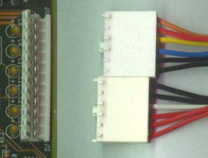
These are the older of the power supplies. They have two 6-pin keyed single-inline connectors that plug into the motherboard right next to each other.
No special requirements are needed to make these work. These are the easiest to use.
"Classic" ATX Power Supply
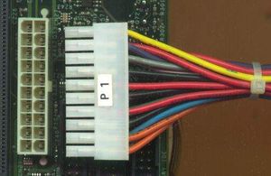
These power supplies can be identified by having a 20 pin dual-inline keyed molex connector that plugs into the motherboard.
To make these supplies work, you need to wire the green wire of the motherboard connector to one of the black wires so that it will turn on when you supply power. Alternatively, connect a switch between the green wire and a black wire, and this will be your main RepRap power switch.
The 3.3V sense wire needs to be connected to +3.3V. This is a brown or orange wire in pin 11 of the connector. It should be connected to 3.3V (orange).
Pinouts
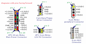
Most connectors have pin numbers on the top, but if not, when viewed from above with the key pointing downwards, pin 1 is in the top left. The number proceeds left to right across the top (pins 1 to 10) and then left to right across the bottom (pins 11 to 20).
- +3.3V (orange)
- +3.3V (orange)
- Ground (black)
- +5Vdc (red)
- Ground (black)
- +5Vdc (red)
- Ground (black)
- PWR-OK (gray)
- +5V VSB standby Voltage (purple). 10mA max.
  10 +12V (yellow)
  11 +3.3V (orange, brown is 3.3Vdc sense)
  12 -12V (blue)
  13 Ground (black)
  14 PS-ON (green). Active low control input.  Connect to ground to turn supply on.
  15 Ground (black)
  16 Ground (black)
  17 Ground (black)
  18 -5V (white)
  19 +5V (red)
  20 +5V (red)
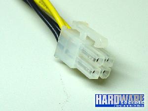
ATX supplies usually also come with a high current 12V output that terminates with a 2x2 keyed connector. You may want to use this output instead.
ATX 2 Power Supply
These power supplies can be identified by having a 24 pin dual-inline keyed connector that plugs into the motherboard.
To make these supplies work, you need to wire the green wire to the black (see ATX supply notes above).
Also, as with the ATX supply the sense wires need to be connected. There will generally be a 3.3V connector (orange or brown on pin 13) which needs to be connected to 3.3V (orange). On the ATX 2 power supplies, there may also be additional sense wires that need to be connected to the corresponding voltage. These are usually thinner wires, and should be connected to a wire of the same colour.
Pinouts
- +3.3V (orange)
- +3.3V (orange)
- Ground (black)
- +5Vdc (red)
- Ground (black)
- +5Vdc (red)
- Ground (black)
- PWR-OK (gray)
- +5V VSB standby Voltage (purple)
  10 +12V (yellow)
  11 +12V (yellow)
  12 +3.3V (orange, brown is 3.3Vdc sense)
  13 +3.3V
  14 -12V (blue)
  15 Ground (black)
  16 PS-ON (green)
  17 Ground (black)
  18 Ground (black)
  19 Ground (black)
  20 -5V (white)
  21 +5V (red)
  22 +5V (red)
  23 +5V (red)
  24 Ground (black)
Troubleshooting
Some power supplies need a load in order to turn on. So without the reprap connected, it may not appear to start up. If you want to test prior to connecting, you may need to put some kind of load on the output first (eg a light bulb or resistor).
Voltage Sensing
The +3.3 VDC remote sensing wire (brown or orange) is connected directly to the orange +3.3 VDC at pin 11 of the power connector (pin 13 if a 2x12). The sense wire will usually be of a lighter gauge (22 AWG) than the power wires (16 or 18 AWG) and its purpose is to monitor the voltage at the connector in order to provide feedback for voltage compensation by the supply.
If your PS has two wires attached to the same pin on the motherboard power connector, orange +3.3 VDC and a brown sense wire on Pin 11 for example, then these two wires should be joined when you make your conversion. Some power supplies may also have sense wires running to the +5 VDC and +12 VDC connector pins. If there are multiple sense wires, then they will usually be of the same color as the primary supply wire, but of a lighter wire gauge. These sense wires will also terminate in a different location on the PS printed circuit board than the heavier supply lines. As with the +3.3 sense wire, these additional wires should also be connected to the corresponding supply lines. Failure to complete these connections may result in your power supply not latching into a Power_On mode when switched on.
-- Main.SimonMcAuliffe - 01 Jul 2006


