PC Power Supply
|
English • العربية • български • català • čeština • Deutsch • Ελληνικά • español • فارسی • français • hrvatski • magyar • italiano • română • 日本語 • 한국어 • lietuvių • Nederlands • norsk • polski • português • русский • Türkçe • українська • 中文(中国大陆) • 中文(台灣) • עברית • azərbaycanca • |
Power supplies (PSUs) built for commodity PCs, typically ATX PSUs, are pretty convenient for supplying RepRap printers and their controllers. They're affordable, made for supplying electronics and can often be salvaged from old PCs. Here we describe on how simple it's to use them, or what to do if it's not entirely trivial.
Contents
- 1 Safety
- 2 Electronics prepared for PC Power Supplies
- 3 Required Minimum Specifications
- 4 Modifying a PC Power Supply for general (RepRap) Usage
- 5 Technical Details
- 6 AT Power Supply
- 7 "Classic" ATX Power Supply
- 8 ATX 2 Power Supply
- 9 Troubleshooting
- 10 Building an affordable power supply
- 11 Simpler permanent modifications
Safety
Generally, power supplies built into PCs are reasonable safe, even when used outside a PC. They have good overload and overheat protection built in. No high voltage parts touchable unless you open the housing. Still, following a few simple rules is a good idea:
- Don't risk spilling fluids into it. A PSU is not the right place to place your coffee cup onto.
- Don't risk metal parts, like screw drivers, falling into it through the venting holes, either.
- Don't open the housing unless absolutely neccessary.
- If you think you have to open the housing, think twice. In almost all cases it's not needed. If you still think you need to do so, disconnect the mains cable and wait at least 10 minutes. There are high voltage capacitors inside which discharge slowly.
- Fully close the housing before connecting mains again.
Electronics prepared for PC Power Supplies
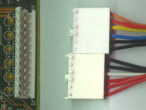
Some RepRap electronics are already prepared to be used with PC power supplies units (PSUs). There you can plug connectors already fitted to the PSU's cables directly into the RepRap board, no modification or opening of the unit required.
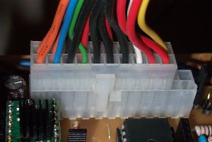
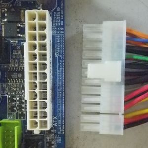
The picture shows a PC PSU with 20 pin ATX connector into an electronics with ATX24 header as an example. Any combination of ATX20 and ATX24 headers and connectors work.
Base Load
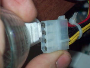
Some ATX PSUs (not all) require a minimum load on the 5 V rail to work properly. Whether your ATX PSU requires a base load or not has to be tried. A symptom of this problem is that the PSU will simply refuse to turn on, it immediately shuts down after being turned on or emits a clearly audible high pitch whine, all unless there is a minimum load on the +5 V rail. Connecting a 4.7 ohms 10 W resistor, an old CD drive or a 12 V light bulb (into the 5 V rail, see picture) are well proven methods to get this load.
See also #Technical Details.
List of PC-PSU enabled electronics
Required Minimum Specifications
This one is a bit tricky, as some PSUs with identical specifications work better than others. Some voltage regulators inside the PSU apparently have no trouble delivering 120 watts to a temperature controlled heated bed, others need to be oversized. With temperature control, the bed is turned on and off at a very quick rate, also known as pulse width modulation (PWM).
- 12V @ 5A for 5 steppers
- 12V @ 2A for a 22W hotend heater (e.g.: J_Head_Nozzle#Heater_Resistor) (or more for a Ceramic_Heater_Cartridge)
- 12V @ 10A for a 120W heated bed or PCB_Heatbed
- 5V @ < 1A for electronics, however some electronics generate their own logic power from their 12V inputs.
- 5V @ 0 to 2A for Balancing_ATX_Supplies or providing a ATX#Base_Load. See PCPowerSupply#Troubleshooting if needed.
In the RepRap forum you can find a number of power supply experience reports. The 5V rail is always oversized (which doesn't matter), attention should be on the 12V rail's capabilities.
Modifying a PC Power Supply for general (RepRap) Usage
This is required for cases where your electronics is not prepared to use unmodified ATX PSUs. It can be as simple as snipping off connectors.
Turning the supply on
After plugging in an ATX PSU into mains electricity and turning on a possible mains switch, there's still no voltage on most of the rails: the PSU is in standby mode, where only the +5 V Standby rail on the 20/24 pole connector is on.
To bring the PSU out of standby mode and get voltages on all rails as well as a rotating cooling fan (this is called softstart, btw), you have to bridge PS ON (green wire) to ground (one of the black wires). A bent paperclip is sufficient for testing purposes, but you'll have to add a proper switch for normal use.
RepRap controllers prepared for ATX PSUs have the required circuitry to softstart the ATX PSU and do not require any additional switches.
Wiring the supply
There are three types of PC power supply you will commonly encounter. Notes for using each are provided here.
You generally only need to connect a wire from black (ground) and yellow (+12 V) to the RepRap. To supply higher current, it is a good idea to connect several of the black wires together to provide ground and several of the yellow wires together.
Color coding
The color coding is universal amongst all of the power supplies:
- Black: Ground
- Red: +5V
- Yellow: 12V
- Orange: +3.3V
- White: -5V (not present on some new supplies)
- Blue: -12V
- Gray: power on indicator
- Purple: +5V standby power output (not needed for RepRap)
- Green: PS_ON power on input.
Technical Details
Minimum Load
Minimum load is one of the possible reasons for the base load requirement. It depends on whether or not your PSU has an underload protection circuit and how this circuit is configured. If even tiny loads on the 12 V rail without a proper load on the +5 V rail cause the PSU to shutdown, some base load (approx. 1 A) is required.
It also brings in an inconvenience: some electrical energy just gets wasted as heat.
Balanced Load
Requirement for a balanced load is another possible reason for a base load requirement. Similarly to the minimum load requirement above, some older ATX PSUs require a load on their +5 V and/or +3.3 V rails to balance the load on the +12 V rail and function properly. A common symptom of this problem is that the unbalanced coils of the +5 V and +3.3 V rails will emit a clearly audible high pitch whine as soon as the +12 V rails is loaded, and the voltage on the +12 V rail will suffer from poor regulation. Possible balancing loads are the same as the ones to provide a minimum load (see above), but may fail to completely eliminate the high pitch whine, and in some cases it is better to just try another more modern ATX PSU. ATX PSUs which are specified as "Haswell ready" should never have this problem.
AT Power Supply
These are the older of the power supplies. They have two 6-pin keyed single-inline connectors that plug into the motherboard right next to each other.
No special requirements are needed to make these work. These are the easiest to use.
Very old AT supplies (and other switching supplies of the early 90s) may mandatory need an external load (see above) - without an external load they'll kill themselves after some 10s. Short background: Without a load the swing didn't start and that killed internal components shortly.
"Classic" ATX Power Supply
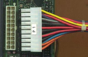
These power supplies can be identified by having a 20 pin dual-inline keyed molex connector that plugs into the motherboard.
To make these supplies work, you need to wire the green wire of the motherboard connector to one of the black wires so that it will turn on when you supply power. Alternatively, connect a switch between the green wire and a black wire, and this will be your main RepRap power switch.
The 3.3V sense wire needs to be connected to +3.3V. This is a brown or orange wire in pin 11 of the connector. It should be connected to 3.3V (orange).
Pinouts
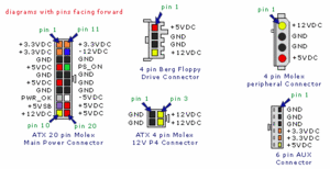
Most connectors have pin numbers on the top, but if not, when viewed from above with the key pointing downwards, pin 1 is in the top left. The number proceeds left to right across the top (pins 1 to 10) and then left to right across the bottom (pins 11 to 20).
  01 +3.3V (orange)
  02 +3.3V (orange)
  03 Ground (black)
  04 +5Vdc (red)
  05 Ground (black)
  06 +5Vdc (red)
  07 Ground (black)
  08 PWR-OK (gray)
  09 +5V VSB standby Voltage (purple).  10mA max.
  10 +12V (yellow)
  11 +3.3V (orange, brown is 3.3Vdc sense)
  12 -12V (blue)
  13 Ground (black)
  14 PS-ON (green). Active low control input.  Connect to ground to turn supply on.
  15 Ground (black)
  16 Ground (black)
  17 Ground (black)
  18 -5V (white)
  19 +5V (red)
  20 +5V (red)
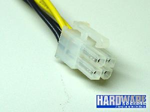
ATX supplies usually also come with a high current 12V output that terminates with a 2x2 keyed connector for the CPU. You may want to use this output instead.
note: The CPU power connector is usually connected to the power supply's second rail while the main(motherboard) connector usually has rail 1 power.
ATX 2 Power Supply
These power supplies can be identified by having a 24 pin dual-inline keyed connector that plugs into the motherboard. Note that the numbering on the connector may vary; on some, they are numbered straight 1-24, on others the original 20 are numbered, then the additional 4 are numbered separately. The instructions below assume the 1-24 numbering.
As with the ATX power supplies, the sense wire needs to be connected. This is the green one, pin 16, and it has to be connected to one of the black ones (ground), usually pin 15.
There may also be additional sense wires that need to be connected to the corresponding voltage. These are usually thinner wires, and should be connected to a wire of the same colour that they are connected to in the connector assembly. A common one is pin 13 (orange or brown) to 3.3V (orange).
Pinouts
  01 +3.3V (orange)
  02 +3.3V (orange)
  03 Ground (black)
  04 +5Vdc (red)
  05 Ground (black)
  06 +5Vdc (red)
  07 Ground (black)
  08 PWR-OK (gray)
  09 +5V VSB standby Voltage (purple)
  10 +12V (yellow)
  11 +12V (yellow)
  12 +3.3V (orange, brown is 3.3Vdc sense)
  13 +3.3V
  14 -12V (blue)
  15 Ground (black)
  16 PS-ON (green)
  17 Ground (black)
  18 Ground (black)
  19 Ground (black)
  20 -5V (white)
  21 +5V (red)
  22 +5V (red)
  23 +5V (red)
  24 Ground (black)
Troubleshooting
Some power supplies need a load in order to turn on. So without the reprap connected, it may not appear to start up. If you want to test prior to connecting, you may need to put some kind of load on the output first (eg a light bulb or resistor). In fact you may need a larger load on the 5V line than is recommended below. See Balancing_ATX_Supplies.
Voltage Sensing
The +3.3 VDC remote sensing wire (brown or orange) is connected directly to the orange +3.3 VDC at pin 11 of the power connector (pin 13 if a 2x12). The sense wire will usually be of a lighter gauge (22 AWG) than the power wires (16 or 18 AWG) and its purpose is to monitor the voltage at the connector in order to provide feedback for voltage compensation by the supply.
If your PS has two wires attached to the same pin on the motherboard power connector, orange +3.3 VDC and a brown sense wire on Pin 11 for example, then these two wires should be joined when you make your conversion. Some power supplies may also have sense wires running to the +5 VDC and +12 VDC connector pins. If there are multiple sense wires, then they will usually be of the same color as the primary supply wire, but of a lighter wire gauge. These sense wires will also terminate in a different location on the PS printed circuit board than the heavier supply lines. As with the +3.3 sense wire, these additional wires should also be connected to the corresponding supply lines. Failure to complete these connections may result in your power supply not latching into a Power_On mode when switched on.
-- Main.SimonMcAuliffe - 01 Jul 2006
Building an affordable power supply
[Taken from http://wiki.ehow.com/Convert-a-Computer-ATX-Power-Supply-to-a-Lab-Power-Supply]
HOW TO CONVERT A COMPUTER ATX POWER SUPPLY TO A REPRAP POWER SUPPLY
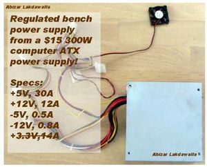
Computer power supplies cost around US $15, but lab power supplies can run you US$100 or more! By converting the cheap (free) ATX power supplies that can be found in any discarded computer, you can get a phenomenal lab power supply with huge current outputs, short circuit protection, and very tight voltage regulation.
Before you begin this process make sure that the PC switching power supply that you buy or salvage will meet your amperage needs. This is an especially critical issue if you intend using high torque NEMA 17 or NEMA 23 stepper motors in your RepRap. I suspect that most RepRaps will be able to get by with a 15 amp supply for +12v. PC switchable power supplies rated at 300 watts and higher can typically meet this kind of demand. It should be noted that the Godzilla RepRap design uses 5 NEMA 17's energised requires 22 amps. You don't start seeing this sort of capacity until you size up to 450 watts and then not always. For systems this large you should always check the PC switchable power supply specifications for the model you intend to use. I was able to get one of this capacity for Godzilla for US$22.95 and could have got one for as little as US$16.95. Shop!
Warning: Line voltage (220V/110V) can kill. If you are in doubt, ask someone who knows what he's doing! Make sure that you have removed the power cord before doing the conversion and have discharged the capacitors by tying the +5V to ground or by shorting the capacitors with the power resistor or with screwdriver. However, the easiest way to discharge the capacitors is to wait a few hours.
Steps
- Unplug the power cord from the back of the computer. "Harvest" a power supply from a computer by opening up the case of the computer, locating the gray box that is the power supply unit, tracing the wires from the power supply to the boards and devices and disconnecting all the cables by unplugging them.
- Remove the screws (typically 4) that attach the power supply to the computer case and remove the power supply.
- Cut off the connectors (leave a few inches of wire on the connectors so that you can use them later on for other projects).
- Discharge the power supply by stripping the insulation of the ends of a black and a red wire and connecting them together.
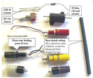
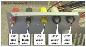
- Get all the parts that you need together, such as the following: binding posts (terminals), a LED with a current limiting resistor, a switch, a power resistor (10 ohm, 10W or greater wattage), and heat shrink tubing.
- Open up the power supply unit by removing the screws connecting the top and the bottom of the PSU case.
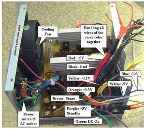
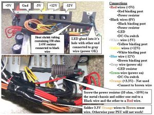
- Bundle wires of the same colors together. IMPORTANT: Make sure that the lone brown sense wire is bundled with the orange wire. If the brown wire is tied to 3.3V, the power supply will produce an output.
- The color code for the wires is: Red = +5V, Black = 0V, Yellow = +12V, Blue = -12V, Brown = Sense (tie to 3.3V), Orange = +3.3V, Purple = +5V Standby (not used), Gray = power is on, and Green = Turn DC on.
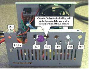
- Drill holes in a free area of the power supply case by marking the center of the holes with a nail and a tap from the hammer. Use a dremel to drill the starting holes followed by a hand reamer to enlarge the holes till they are the right size by test fitting the binding posts. Also drill holes for the power ON LED and a Power switch.
- Screw the binding posts into their corresponding holes and attach the nut on the back.
- Connect all the pieces together.
- Connect one of the red wires to the power resistor, all the remaining red wires to the red binding posts;
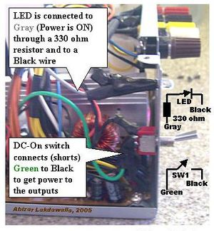
- connect one of the black wires to the other end of the power resistor, one black wire to a resistor (330 ohm) attached anode of the LED, one black wire to the DC-On switch, all the remaining black wires to the black binding post;
- connect the white to the -5V binding post, yellow to the +12V binding post, the blue to the -12V binding post, the gray to the cathode of the LED;
- connect the green wire to the other terminal on the switch; and hook up the orange wires with the brown.
- Make sure that the soldered ends are insulated in heatshrink tubing.
- Organize the wires with a lot of electrical tape.
- Make sure that all the connections look good. Put a drop of superglue to stick the LED to its hole. Put the cover on.
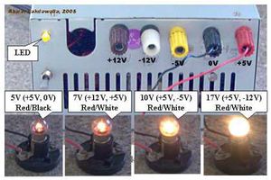
- Plug in the IEC power cord into the back and into an AC socket. Switch on the main switch on the PSU. Check to see if the LED light comes on. If it has not, then power up by flipping the switch that you had placed on the front. Plug in a 12V bulb into the different sockets to see if the PSU worked, also check with a digital voltmeter. It should look good and work like a charm!
Tips
- OPTIONS: You don't need an additional switch, just connect the green and a black wire together. The PSU will be continuously on. You also don't need an LED, just ignore the gray wire. Cut it short and insulate it from the rest.
- In the older ATX power supplies, the brown sense wire needs to be attached to the 5v wire for the PSU to work.
- In some cases, you may find that there is no brown wire. However, if you get a pin-out of an ATX motherboard connector, you can see which wire is the sensor wire (pin 11.) If not brown, this wire is probably orange.
- If the power supply does not work, that is, no LED light, check to see if the fan has come on. If the fan in the power supply is on, then the LED may have been wired wrong (the positive and negative leads of the LED may have been switched). Open the power supply case and flip the purple or gray wires on the LED around (make sure that you do not bypass the LED resistor).
- If you are not sure of the power supply, test it in the computer before you harvest. Does the computer power on? Does the PSU fan come on? You can place your voltmeter leads into an extra plug (for disk drives). It should read close to 5V (between red and black wires). A supply that you have pulled may look dead because it does not have a load on its outputs and the enable output may not be grounded (green wire).
- The power resistor needs to be attached to the metal body as it gets pretty warm and needs to be kept cool by conduction. If you cannot attach the resistor with a screw, attach the resistor by tying it to a ventilation slot with twist ties or large diameter copper wire.
- Feel free to add some pizzaz to the dull gray box.
- You can also convert this to a VARIABLE POWER SUPPLY - but that is another article (hint: Uses a 317 IC with power transistor).
- The voltages that can be output by this unit are 5v (+5, 0), 7v (+12, +5), 10v (+5, -5), 12v (+12, 0,) 17v (+5, -12) and 24v (+12, -12) which should be sufficient for most electrical testing.
- You can add a 3.3 volt output to the supply by hooking the orange wires to a post (make sure the brown wire remains connected to the orange bundle) but beware that they share the same power output as the 5 volt, and thus you must not exceed the total power output of these two outputs.
Things You'll Need
- An obsolete computer with an ATX 250W, 300W or 400W power supply.
- Wire cutters, needle nose pliers, drill, reamer, soldering wire, soldering iron, electrical tape, heat shrink tubing
- Binding posts for output terminals, LED, current limiting resistor for the LED, power resistor to load the power supply, a low wattage switch.
Simpler permanent modifications
As discussed here.
To prevent the inevitable trip over loose wires, it's a good idea to make your wiring more permanent once you have confirmed the power supply (PSU) to work. This is one way of doing so.

- Design features.
- Duct tape to avoid any potential hooking of wires, and to secure the switch. Don't tape the air intakes shut, as air flow is needed.
- A big kill switch for easy access.
- The fan on this 250w PSU is very quiet, so a LED was added to show power on.
- Unused wires are spared and kept in a box on the side, if they are to be used later. If you know you don't want them, you can cut them off to make it even neater, just remember to insulate the ends to avoid short circuits.
- Easy connection to the reprap by the original molex connector.
- A cable tie holds the molex connector to avoid ripping wires when unplugging.
- Wiring
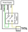
- PS_ON to GND turns the PSU on; PS_ON ungrounded turns it off.
- The cut to the 12v line will turn the power off a few insignificant milliseconds faster as some charge is held in the capacitors of the PSU. But if you don't have a dual / ground switch you really want to use, you can just as well leave the 12v line be.
- If you have a female molex connector around, you can use the molex connector on the PSU directly for easy connection on and off.
- Remember to test the construction and outputs with a voltmeter before you connect it to your RepRap!
- Other ideas
- Add a trip safe wire connector to the RepRap, so if you do trip you won't destroy the electronics.
- Make several switches and connectors so you can connect more machines to one PSU.
- More duct tape.
