Portabee
Release status: Working

| Description | Printrbot variant that could be packed in a laptop bag
|
| License | GPL
|
| Author | |
| Contributors | |
| Based-on | |
| Categories | Printrbot variations
|
| CAD Models | hhmmm...
|
| External Link |
The portabee, is a Printrbot / Wallace variant which was designed to be able to be packed into a laptop bag. It has a 3mm FR4 matte black heated longbed, default gen6.d electronics which allows direct SD card printing, use of heated longbed as well as a channel for a micro fan. The build area is 120mm x 120mm x 120mm.
Contents
- 1 Specifications
- 2 Building Documentation
- 3 Where To Purchase
- 4 Where To Get Source Files
- 5 Updated information for 2021
- 5.1 Latest corporate homepage from 2018
- 5.2 Official setup page
- 5.3 Firmware
- 5.4 slic3r settings
- 5.5 Detailed review and usage guide
- 5.6 Portabee print troubleshooting guide
- 5.7 Basic configuration
- 5.8 Tips on using and printing with Portabee
- 5.9 Repairs and Improvements
Specifications
- Printed Parts: ???
- Non-Printed Parts: ???
- Printing Size: 12cm x 12cm x 12cm (apprx. 4.75"x4.75"x4.75")
- Material Costs: ???
- Precision: ??? (position), ??? (printing)
- Speed: Positioning speed: ??? . Printing speed: recommended 40 mm/s, but up to 450 mm/s has been tested.
Building Documentation
as looked up at RomScraj.com (if documentation links are outdated, look up again new links).
Where To Purchase
- http://romscraj.com - USD 490 unassembled, USD 640 assembled
- http://portabee3dprinter.com - USD 499 unassembled, USD 699 assembled
Where To Get Source Files
Updated information for 2021
This somewhat older printer unfortunately seems no longer to be available, making it hard to find relevant information. This section will summarise relevant information that is still available on the web as of 2021.
Latest corporate homepage from 2018
https://web.archive.org/web/20181031151948/http://portabee3dprinter.com/
Official setup page
https://web.archive.org/web/20180919005414/http://portabee3dprinter.com/support/portabee-kit-docs/
This page includes:
- Assembly manual
- First print using Pronterface and Cura software
- STL files for printer parts
- Upgrades for the printer such as:
- Y-axis brace
- Filament guide
- Fan frame
Firmware
https://web.archive.org/20160604072127/http://portabee3dprinter.com:80/portabee-firmware-guide/
slic3r settings
The following recommended settings are mostly from the file https://github.com/downloads/Lunavast/Portabee/config_300_portabee_2.ini, with some minor corrections (see below). Save this file and then import it into slic3r via File->Load Config.
Note (corrections): the original file had a mistaken "M1140 S0" command. This should be "M140 S0", to turn off the heated bed.
acceleration = 0
bed_size = 120,120
bed_temperature = 0
bridge_fan_speed = 100
bridge_flow_ratio = 1
bridge_speed = 40
brim_width = 0
complete_objects = 0
cooling = 0
disable_fan_first_layers = 1
duplicate = 1
duplicate_distance = 6
duplicate_grid = 1,1
end_gcode = M104 S0 ; turn off temperature\nM140 S0\nG28 X0  ; home X axis\nM84     ; disable motors
extra_perimeters = 1
extruder_clearance_height = 20
extruder_clearance_radius = 20
extrusion_axis = E
extrusion_multiplier = 1
extrusion_width = 0
fan_always_on = 0
fan_below_layer_time = 60
filament_diameter = 3.0
fill_angle = 45
fill_density = 0.2
fill_pattern = rectilinear
first_layer_bed_temperature = 0
first_layer_extrusion_width = 0
first_layer_height = 100%
first_layer_speed = 36%
first_layer_temperature = 0
g0 = 0
gcode_arcs = 0
gcode_comments = 0
gcode_flavor = reprap
infill_acceleration = 50
infill_every_layers = 1
infill_extrusion_width = 0
infill_speed = 40
layer_gcode =
layer_height = 0.36
max_fan_speed = 100
min_fan_speed = 35
min_print_speed = 10
notes =
nozzle_diameter = 0.5
output_filename_format = [input_filename_base].gcode
perimeter_acceleration = 25
perimeter_speed = 36
perimeters = 2
perimeters_extrusion_width = 0
post_process =
print_center = 60,60
randomize_start = 1
retract_before_travel = 2
retract_length = 1
retract_lift = 0
retract_restart_extra = 0
retract_speed = 10
rotate = 0
scale = 1
skirt_distance = 3
skirt_height = 1
skirts = 1
slowdown_below_layer_time = 15
small_perimeter_speed = 36
solid_fill_pattern = rectilinear
solid_infill_speed = 40
solid_layers = 3
start_gcode = G28 ; home all axes
support_material = 0
support_material_angle = 0
support_material_pattern = rectilinear
support_material_spacing = 2.5
support_material_threshold = 45
support_material_tool = 0
temperature = 0
threads = 2
top_solid_infill_speed = 38
travel_speed = 128
use_relative_e_distances = 0
z_offset = 0
Maximum print speed
The above settings file sets the maximum print speed to 40 mm/s. Maximum print speed may be around 450 mm/s. See https://reprap.org/wiki/Portabee#Speed_limitations.
Retraction
The above settings file sets retraction distance to 1 mm, with retraction speed of 10 mm/s.
Retraction speed of 15 mm/s was also confirmed to work in practice.
However, retraction speed of 100 mm/s was too high, and caused the extruder motor to slip during retractions. Retractions, which ordinarily result in a large rotation (tens of degrees) of the large 53-tooth extruder gear, resulted in only a small rotation (a few degrees) of the gear, plus a loud whining sound from the extruder motor. The final result was extreme stringing on the print, because retraction was effectively not working. Probably, the Portabee extruder motor is not capable of providing the required high torque to retract the filament at 100 mm/s.
In the above test with failed high-speed 100 mm/s retraction, a modified extruder block was used that had a somewhat loose grip on the hobbed bolt (because the extruder block was printed with larger holes using slic3r's "xy size compensation" parameter set to -0.15 mm). It is possible that an extruder block with smaller, tighter holes, and a tighter grip on the hobbed bolt and hence a tighter grip on the filament, might be able to perform retractions at higher speed.
Detailed review and usage guide
Includes images of sample prints from the Portabee, troubleshooting guide, and tips about what to expect.
http://www.cygig.com/2013/08/review-portabee-3d-printer-most.html
Alternate URL: https://forums.vrzone.com/chit-chatting/2904838-review-portabee-3d-printer-the-most-afforable-singapore.html
Portabee print troubleshooting guide
https://i.imgur.com/iSEdqeM.jpg
Basic configuration
Basic hardware configuration
Insert filament
- Fully loosen the 4 nuts on idler block until the nuts are at the end of their respective screws, but do not remove the nuts from the screws. This step is easier if you replace the original hex nuts (which must be adjusted with a tool) with finger-adjustable knurled nuts (https://en.wikipedia.org/wiki/Knurled_nut).
- Pull idler block away from the extruder so that there is a clear path from the filament feed hole at the top of the extruder, all the way down to the hot end. The path for the filament should not be obstructed by the extruder bearing (because the idler block has been pulled away from the extruder so as not to block the filament feed path).
- Heat the hot end to the desired extrusion temperature (180 degrees for PLA).
- Push the filament all the way through the extruder hole, all the way down until it reaches the end of the hot end. The filament should be unobstructed by the extruder's internal bearing. As you push down on the filament, it should melt and ooze out of the hot end.
- Tighten the 4 nuts on the idler block, so that the extruder's bearing now grips the filament (by pressing it against the extruder's internal toothed brass gear).
- Clean the tip of the hot end.
Remove filament
- Fully loosen the 4 nuts on idler block until the nuts are at the end of their respective screws, but do not remove the nuts from the screws.
- Pull idler block away from the extruder, so that the extruder no longer grips the filament.
- Set the hot end to 90 degrees (for PLA) to soften, but not melt, the filament, and wait for the temperature to stabilize.
- After the temperature stabilizes, pull the filament out vertically from the filament feed hole.
Basic firmware configuration
Temperature setting, PID tuning
If, after setting the desired temperature in Pronterface, the hot end or the heated bed cannot reach the desired temperature, then PID tuning is necessary. See https://reprap.org/wiki/PID_Tuning.
Calibrate E-steps
Updating the firmware
- warning: multiple board variants
Basic software configuration
Speed limitations
- Limit speed to less than 40 mm/second, or else print quality may suffer.
- Reference 1: Initial slow speed for test prints is recommended as 30 mm/second. https://web.archive.org/web/20180919005414/http://portabee3dprinter.com/support/portabee-kit-docs/
- Reference 2: slic3r configuration file at https://github.com/downloads/Lunavast/Portabee/config_300_portabee_2.ini limits maximum print speed to 40 mm/second.
- Reference 3: Portabee review at https://reprap.org/wiki/Portabee#Detailed_review_and_usage_guide states that print quality suffers above 40 mm/second.
A Youtube video exists (https://www.youtube.com/watch?v=hRRoJJtF4qM) showing the Portabee printing at 450 mm/s. In practice, it was observed that high-speed printing seemed to lead to a complete loss of extrusion after a few minutes; the hobbed bolt was no longer able to grip the filament and drive it forward (for extrusion) and backward (for retraction) at the required high speeds; filament movement and extrusion then stopped. It is possible that tightening the idler block nuts for a very tight grip on the filament might allow high-speed filament motion and high-speed printing. This likely also requires that the holes in the extruder block itself should tightly fit the hobbed bolt and bearings; any looseness caused by oversized holes in the extruder block might reduce the ability of the extruder to drive the filament at high speed. It may be necessary to print a couple of replacement extruder blocks, with varying hole sizes, to find the smallest hole size that ensures the tightest fit.
Temperature configuration
It seems to work better if you manually heat the nozzle and confirm good filament flow, instead of allowing the slic3r-generated gcode to automatically heat the nozzle and wait for the nozzle to reach the appropriate temperature. (However, see later note below about untested "Method 2" for ensuring good filament flow before the print.) The reason is that the slic3r-generated gcode, which attempts to control the nozzle temperature, may wait unpredictably long before starting the print, and this unpredictable wait may lead to poor flow and insufficient extrusion at the beginning of the print.
- In slic3r, enable printing one skirt around the object.
- In slic3r, set temperature settings to zero, meaning the generated gcode will ignore the temperature.
- Warning: this means it will be possible to start the print from the generated gcode instantly, even if the nozzle is cold. This could damage the extruder gears. Always heat the nozzle to extrusion temperature before starting the print.
- In Pronterface, manually set the nozzle temperature to extrusion temperature, before the print.
- Manually extrude enough filament before the print to ensure it flows smoothly.
- As soon as smooth filament flow has been confirmed, immediately start the print (with the gcode file from step 1 that ignores temperature settings).
- The printer should immediately start printing and the first skirt should be drawn. The skirt should show perfectly smooth and continuous extrusion, leading to a clean and unbroken skirt line that adheres well to the print bed.
- Abort the print immediately if the skirt shows gaps or other signs of poor extrusion. Then, increase the Z height to about 4 cm, and again manually extrude a few cm of filament until the flow again becomes smooth. Also, check the bed level and home Z height to ensure good adhesion of the initial skirt and first layer.
Tips on using and printing with Portabee
Before moving the printer
- Confirm all screws and belts are tightened appropriately. Items prone to come loose due to vibration in normal use are:
- The set screw on the plastic drive gear on the extruder motor shaft
- The set screws on the Z leadscrews
- The screws holding the smooth Z rods in place
- The nuts securing the Y-axis support rods to the plastic base
- The screws holding the motors (X, Y, and Z) in place
When moving the printer
- Confirm all screws and belts are tight.
- Use two hands, one to grasp each z stepper motor. Be careful not to twist the assembly.
- Do not grasp the Z rods (either the Z leadscrews, or the smooth Z rods), because this may cause them to become loose and/or misaligned.
Before turning on the printer
- Confirm all screws and belts are tight.
- Prepare an emergency-stop switch to cut the power to the printer immediately (or be prepared to yank the power cord if needed).
- Confirm the end stop switches are physically mounted so that they will activate when the print head reaches the start of each axis. If the switches are wrongly mounted so they do not activate, then the motors may try to drive the print head past the physical dimensions, causing a crash into and physical damage of plastic parts securing the X, Y, and/or Z axes.
After turning on the printer
- Turn on the extruder barrel fan with M106. It should always be on.
- Adjust the Z endstop so the nozzle is an appropriate distance from the print bed.
- Using Pronterface software, move the print head to the home position on the X, Y, and Z axes. Be prepared to cut power instantly (via the emergency-stop power switch) if the print head crashes into the printer sides or the print bed.
- Level the print bed.
- Calibrate the E-steps.
- Recommended starting value is 514 (reference: https://web.archive.org/web/20180919005414/http://portabee3dprinter.com/support/portabee-kit-docs/).
- Should be possible to set via M92 command (reference: https://marlinfw.org/docs/gcode/M092.html).
Before starting the print
- Ensure there is about a 1 mm air gap between the base of the 9-tooth drive gear and the metal housing of the motor. The base of the 9-tooth drive gear should not be flush against the motor housing. This is also indicated in the Portabee assembly guide. If the necessary 1 mm air gap is not present, then the 9-tooth drive gear seems to form a very tight seal against the motor housing, which prevents air from escaping and may lead to motor overheating. After prolonged operation without the necessary 1 mm air gap, a buildup of black grease powder forms around the motor shaft and the base of the 9-tooth drive gear. This may be a sign of overheating, possibly caused by the air-tight gap when the 9-tooth drive gear is incorrectly positioned flush against the motor housing.
- Ensure the lock screw (grub screw), that holds the 9-tooth drive gear onto the extruder motor's shaft, is very tight (though over-tightening may break the 9-tooth plastic gear). This screw may gradually come loose during a print due to vibration. If the lock screw gradually loosens during a print, then gradually the motor will start to slip, and extrusion will suddenly stop in the middle of the print. Also see https://reprap.org/wiki/Portabee#Preventing_slip_of_the_extruder.27s_9-tooth_drive_gear
- Load your gcode file (created with your slicer software, such as slic3r) into Pronterface.
- Ensure the print dimensions do not exceed the print bed size (12cm x 12cm x 12cm), or else the motors may try to drive the print head past the physical dimensions, causing a crash into and physical damage the X, Y, and/or Z axes and/or the print bed.
- Ensure that filament flows freely.
- Method 1, manual adjustment (easy)
- Confirm the extruder barrel fan is always on; if not, turn it on with M106.
- Manually heat the hot end to desired temperature.
- Manually set Z to 4 cm above the print bed, and repeatedly extrude filament until it flows smoothly.
- After the filament flows smoothly, immediately (within a few seconds):
- Clean the excess filament from the print bed.
- Clean the nozzle of excess filament (e.g. wipe it quickly with a thick paper towel, taking care not to get burned by the hot end!).
- Start the print. If you wait too long (a minute or more) after the smooth filament flow begins, then the flow may again become poor, requiring re-extrusion to get the filament flowing freely again.
- Method 2, fully automated (advanced)
- Mount the print bed on springs as described later in this page.
- At the end of each print, use custom gcode to execute a large retraction (15 mm may be a good starting point). This should mostly prevent any filament from oozing out of the nozzle, and the nozzle should remain almost completely clean after a print. However, a small drop of filament, perhaps 1 mm, may still ooze out of the nozzle and harden. Example ending gcode:
M104 S0 ; turn off extruder temperature
M140 S0 ; turn off bed temperature
G28 X0 ; home X axis
M84 ; disable motors
M106 ; keep barrel fan on
G92 E0 ; reset extruder
G1 E-15.0 F1200 ; retract 15mm - At the beginning of each print, use the (default) gcode to home all axes, including the Z axis. This will place the cold nozzle directly against the bed. Because there may be a small blob of hardened filament on the tip of the cold nozzle, the added length of this blob will cause pressure against the print bed when the nozzle is returned to the Z=0 position. This is why the print bed should be mounted on springs, as mentioned above -- to absorb the extra force caused by the extra blob of filament being pushed onto the print bed.
- At the beginning of a print, use the (default) gcode to heat the nozzle and wait until it reaches extrusion temperature. Thanks to the almost clean nozzle, practically no filament should ooze out of the nozzle, and the nozzle should remain clean. Furthermore, because the nozzle is pressed right up against (or almost against) the print bed, this will also minimize filament oozing. The result should be that the nozzle stays almost completely clean as it reaches extrusion temperature. Example starting gcode:
M104 S175 ; set temperature
m106 ;turn barrel fan on
G28 ; home all axes
M109 S175 ; wait for temperature to be reached - Use (default) gcode to print several skirts around the object, before printing the object itself. Due to the end-of-print retraction, the first few skirts will suffer from under-extrusion. Therefore, it is important to print several skirts to ensure that enough filament is extruded to ensure a good flow, before the main object itself is printed. The slic3r software has an option to guarantee that the skirts extrude a certain user-specified length of filament. For an end-of-print retraction of 15 mm, a beginning-of-print skirt using 35 mm of filament might be good -- the 35 mm of filament extrusion should be enough to (a) compensate for the end-of-print retraction and (b) to start a consistent and smooth flow of molten filament before the print.
- At the end of the print, again use custom gcode to execute a large retraction.
- The whole key to this automated process is to ensure that the nozzle is always kept clean, so that manual extrusion and manual clean-up of the nozzle after manual extrusion is no longer needed.
- If heating of the bed is required, that step should be included in the above procedure. Alternatively, the bed can be heated manually before executing the above steps.
- Method 1, manual adjustment (easy)
During the print
- Confirm the extruder barrel fan is always on.
- If the fan stops when the print starts:
- Abort the print -- in Pronterface, press "Pause", then "Reset printer".
- Turn on the fan with M106.
- In slic3r, check the option to turn the fan always on.
- Re-slice the 3D model, re-import into Pronterface, and try printing again. This time, the fan should be on.
- If the fan stops when the print starts:
After the print
- Confirm the extruder barrel fan is still on after the print, to prevent heat from creeping up the hot end and possibly clogging the hot end.
- If the fan stops when printing stops:
- Manually turn on the fan with M106.
- In slic3r, add custom gcode at the end of the print to turn the fan always on, with M106.
- If the fan stops when printing stops:
Printing replacement parts for the Portabee
The below notes apply to using PLA filament at 190 degrees.
- Printing the small 9-tooth gear (9-tooth-drive-gear.stl)
- This gear cannot be printed by itself. The small gear teeth layers print so quickly that they are still hot when the next layer is printed on top of them. This leads to overheating and deformation.
- Method 1: Print one copy of the gear with a very high (1000 layers) skirt placed at 3 cm distance from the object. While the large skirt is printing (for every layer), the printed gear teeth layer has time to cool. This seems to give the best quality. The printer does very few retractions, and the flow of filament is fairly constant, leading to a solid appearance of the gear teeth.
- Method 2: Print 2 or more copies of the gear, separated by some distance on the print bed. While the next gear's teeth are printing, the previous gear's teeth have time to cool. However, this method seems to give slightly lower quality (than the tall-skirt method above), with the gear teeth showing signs of underextrusion and weakness. The printer does many retractions when moving between the print areas for each copy of the gear, and after the retraction, the filament flow is probably insufficient when the printing starts again for the small gear teeth. This might be fixed with careful tuning of retraction parameters.
- Issues with too-small hole diameter
- For parts that must slide onto a motor shaft (like gears, or the Z-shaft couplings for the Z-axis threaded rods), or for parts that must accommodate bolts (idler block, extruder block, etc.), the default print settings will likely lead to holes that are too small to allow the motor shaft or bolt to pass through the hole.
- The slic3r setting for "xy size compensation" (Print Settings -> Advanced) can make holes bigger by moving all perimeters towards or away from the infill. Moving all perimeters towards the infill (with a negative value for xy size compensation) will make the hole bigger. A value of -0.15 mm could be a starting point.
- Do not use "xy size compensation" for gears. Although it conveniently makes the center hole of the gear larger, it also shrinks the outer gear teeth perimeters inwards, meaning the gear teeth are smaller. This could affect fit of gears. In this case, it is better not to use xy size compensation in slic3r, and instead to alter the original 3D model to make the center hole slightly larger (perhaps 0.4-0.6 mm larger in radius). This can be done on STL files, for example, by creating a cylinder object to represent the larger hole, and then "subtracting" the cylinder geometry from the original object with a Boolean modifier, thus creating a larger hole with the cylinder's diameter. Blender is one software that can do this.
- For small gears like the extruder's 9-tooth drive gear, enlarging the center hole may cause the slic3r software to eliminate the central supporting wall, which would cause the small gear teeth to become individual, disconnected teeth with no central support. This is because slic3r detects that the central supporting wall is thinner than can be created with a single string of filament, and therefore slic3r removes this thin central supporting wall. The solution is to disable "detect thin walls" in slic3r, which forces slic3r to print the thin structural wall, even though the printed wall width will be thicker than specified in the 3D data.
Repairs and Improvements
Replacing the hot-end heater
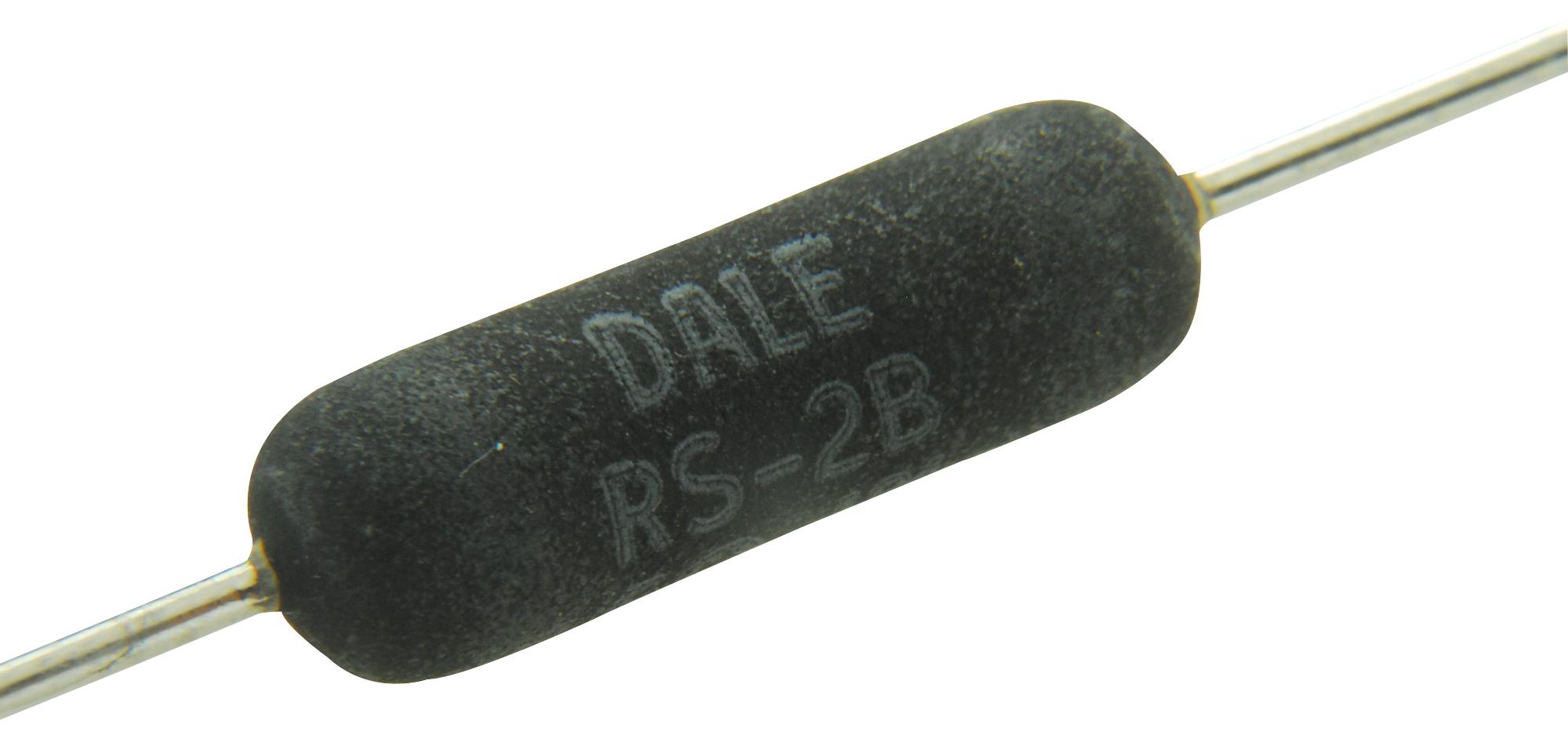
The hole in the heater block to accommodate the heater is 5 mm in diameter. The following 3 watt, 5 ohm, 4.7 mm diameter, silicone-coated, wire-wound resistor (Vishay RS series, RS02B5R000FE12) has been confirmed to fit into the Portabee's heater block and has been confirmed to function properly as a heater.
Datasheet: https://www.mouser.com/ProductDetail/Vishay-Dale/RS02B5R000FE12/?qs=SpUj42xpVX7gyt57C8gJVQ== , https://www.mouser.com/datasheet/2/427/rsns-1762136.pdf
Image: https://www.newark.com/productimages/large/en_US/65K2685-40.jpg
To improve heat transfer from the resistor to the heater block, a bit of aluminum foil can be wrapped around the center of the resistor to make it thicker (being careful not to allow the foil to touch either of the resistor's conductive leads). With a few turns of aluminum foil, the resistor will fit snugly into the 5 mm-diameter hole in the heater block. When first activating the heater, there may be some some smoke as some insulation or other materials burn off. After a minute or two, the smoke stops, and the resistor functions normally as a heater.
Leveling the print bed
- Replace the upper locking nuts with wing nuts or thumb nuts for easier adjustment by hand.
- Replace the lower locking nuts with springs.
- Clip a glass pane on top of the print bed for a flatter surface (since the original print bed, with 4-point leveling, may warp and become uneven)
Releasing the idler block
- Replace the M4 nuts with M4 knurled nuts (thumb nuts) that can be gripped and loosened or tightened by hand.
- This makes it much easier/faster to loosen the idler block to enable removal or insertion of filament.
Preventing slip of the extruder's 9-tooth drive gear
- Drill a small cavity onto the round motor shaft, so that the lock screw (grub screw) can grip the motor shaft. Reference: https://www.igorkromin.net/index.php/2014/11/30/portabee-3d-printer-extruder-motor-latch-mod/
Replacing the electronics board
The gen6.d board used in the original Portabee is no longer available for purchase. Other electronics boards can also be used. For example:
Arduino + RAMPS 1.4 shield
MKS GEN board
(add more here later)