Power Distribution and Communications Board v1.3
Contents
Power and Communications Board v1.3
Note: development on Kicad boards should be done in the electronics/powercomms directory in subversion
Schematic
Changes (Done)
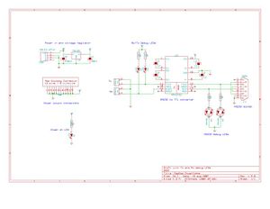
- Add debug LED's to TTL Tx/Rx lines (nophead)
- Add debug LED's to RS232 Tx/Rx lines (nophead)
PCB Layout
TODO List
- Make .100" holes slightly bigger
- give the .100 connectors a proper silkscreen for Tx/Rx as well as power.
- The holes for the C6 capacitor are slightly too close together so the legs have to be bent to fit into the holes and so it isn't seated flush with the board (or in my case even level).
- Fastener holes: ensure clearance fit for 1/8" (3.125mm) diameter shank (Imperial equivalent of M3). Dia 3.5mm should do it.
- Fastener washer space: ensure circuits avoid the radius of an M3 washer on the fastener holes (metal washers might short the circuit).
General TODO
- Test LED modifications on v1.2.1 board with 'green wire' mods.
Technical Documentation
- PowerComms 1.3.0 2007-08-19 schematic as JPG:
- [[File:PowerCommsBoard 1 3-comms and power distribution-sch.pdf: PowerComms 1.3.0 2007-08-19 schematic as PDF|thumb]]
