Prusa Mendel Assembly (iteration 2)/es
Antes de empezar
Antes de ensamblar el Prusa Mendel, asegúrate de disponer de todas las piezas necesarias. Para obtener el listado de todos los materiales, visita: Prusa Mendel.
Notas:
- Este documento todavía está en desarrollo.
- These instructions follow making a PLA based Iteration 2, where integrated bushings are included as part of the RP objects. The design officially supports different bearing combinations, including brass bushings, felt, and linear bearings. RP parts that are for different bearing types will look different and require additional steps but the primary assembly remains essentially the same.
- Source STL files for the printed parts are available from the prusa mendel github repository
- TODO: Merge contents of Kliments Pastebin: http://pastebin.com/t8LcB1du
- Although most steps are absolutely harmless when done right, you still might want to take precautions for your Health and Safety.
- In this manual it is assumed that your X and Z smooth rods are 405mm each and the Y smooth rods are 425mm
The resulting threaded rod lengths are:
1x 450mm - low center rod
2x 440mm - top rods
6x 400mm - frame vertex
4x 320mm - lower rods for front and back side
2x 250-300mm - Z threaded rods
Instrucciones de montaje
Assembling the X-axis
Parts Required
- 1 RP x-end-motor

- 1 RP x-end-idler

- 2 405mm smooth rods (420mm in recent instructions)
- 3 M3x10 bolts
- 1 608 bearing
- 2 M8x30 fender/mudguard washers
- 1 50mm M8 threaded rod and 1 M8 nut or 1 M8x25 or longer bolt
- 3 M8 washers
- 1 M8 nut
- 3 LM8UU Linear Bearings
Instructions <videoflash>K9bXwOZOXps</videoflash>
- Drill out the center hole in the hexagonal section of the x-end-idler and x-end-motor parts to 8mm, if it is not already this size.
- Drill out the 4 holes into which smooth rod pieces will be inserted. (Using a reamer is more precise than using a regular bit)
- Take the x-end-idler part. Check the size of the hole on the flat, thin side surface. If it is 4mm in diameter, enlarge it using a file until it's 8mm in diameter.
- Place the x-end-motor and x-end-idler parts 50cm apart, so that the hexagonal sections are facing each other. The x-end-motor should be on the left and the x-end-idler should be on the right
- Slide the two 420mm smooth rods into the x-end-idler part.
- Look at your X Carriage and determine which side is the front and which side is the back. Then, look at the bottom of the X Carriage and see which side has a slot for 1 linear bearing and which side has a slot for 2 linear bearings. Place 2 linear bearings on one of the 420mm smooth rods and 1 linear bearing on the other depending on the proper orientation of the X Carriage
- Slide the other ends of the rods into x-end-motor part. The hexagonal sections of the motor and idler parts should still be facing each other.
- Make sure the rods are seated as far as they will go into the x-ends.
- Thread an M8 nut onto one end of the 50mm threaded rod, if not using a bolt.
- Put the following parts in this order onto the free end of the threaded rod (behind the nut) or M8 bolt: 1 fender washer, 1 M8 washer, 1 608 bearing, 1 M8 washer, 1 fender washer.
- Thread the free end of the threaded rod into the side of the x-end-idler part. The bearing should be on the outside. Put an M8 washer and an M8 nut on the inside and tighten.
Frame Triangles
This step takes about 15 minutes per triangle, for a total of 30 minutes.
There is a triangle on each side of the Prusa RepRap. You will need to make two of these and then connect them together (in the next steps) to form the Prusa frame. Each side is an equilateral triangle with a frame vertex on each corner. You can use either footed or non-footed vertices to build this. (The footed ones look better, but are not critical.) The instructions assume you are using footed vertices.
Parts Required (per triangle)
- 2 RP footed frame vertices

- 1 RP frame vertex (non-footed)

- 1 RP bar clamp

- 3 400mm M8 threaded rods
- 14 M8 nuts
- 14 M8 washers
<videoflash>-PFy4KhW9gE</videoflash>
- Take one of the 400mm threaded rods, and slip an M8 washer onto the middle of it.
- Take the RP bar clamp (the U-shaped bit with the two holes) and slide the threaded rod through the two holes until the clamp sits next to the washer.
- Slide another washer onto the rod from the other side.
- Thread two M8 nuts onto either side of the clamp, until they are next to the washer, but do not tighten them yet.
- Thread another two nuts on each side of the rod, followed by washers. See the picture for what it should look like. <flickr>5188262096|thumb|right|m|The bar clamp on the threaded rod.</flickr>
- Slide the rod through the wider bottom (footed) side of two vertices. Make sure the feet point in the same direction, and the bulge on the non-footed sides of the vertices point outwards.
- Place another washer and nut on the other side of the vertex. Tighten, but not too much. We'll need a bit of flexibility here still.
- Take another 400mm M8 threaded rod and place a nut followed by a washer at each end.
- Place one end of the threaded rod into the one of the two footed frame vertices. It should be in the same plane as the first threaded rod. Fix it in place with a washer and nut. You should now have two sides of the equilateral triangle.
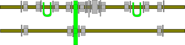
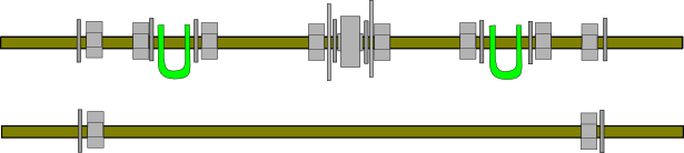
- Take the third piece of threaded rod and put a nut and washer on each end. Place it in the other footed vertex and fix it in place with a washer and nut. You should now have a triangle of threaded rods with two footed vertices on two of the corners, nothing in the third corner, and a bar clamp between the two vertices.
- Adjust the nuts around the bar clamp (but do not crush the bar clamp together yet) until it's approximately in the middle of the rod. Leave the nuts there loose. See the photo for what you should have at this point.
- That's it, that's one of the triangles done. Repeat the entire procedure for the second triangle.
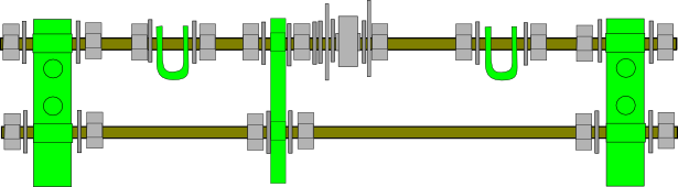
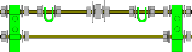
- After you have done the second triangle, you need to make sure that both triangles are the same. To make sure the holes line up, you can lay the triangles on top of each other and insert six M8 bolts through the each hole in the vertices. When they all line up, tighten all the bolts.
Next we will connect the two frame triangles to form the Prusa RepRap frame. The easiest way to do this is to thread everything onto the front and rear threaded rods and attach those to the triangles first, and then thread the top rods through. That's the method the instructions below will follow.
Front Threaded Rods
This step takes about 30 minutes.
These two threaded rods are used to connect the front/bottom vertex of each triangle as well as to attach the y stage bars and y motor bracket to the frame.
Parts Required
- 2 assembled frame vertex triangles
- 2 RP bar clamps
- 1 RP y motor bracket

- 18 M8 nuts (or 16 under the described modification)
- 19 M8 washers (or 17 under the described modification)
- 2 M8x30 fender/mudguard washers
- 1 608 bearing
- 2 294mm threaded rods
Instructions <videoflash>9ut45Pe9gkw</videoflash>
- Thread the bottom rod first. Thread an M8 nut onto the middle of the rod. Slide an M8 washer next to it.
- Thread the rod through the bottom hole of the RP y motor bracket. The bottom hole of the bracket is the larger one on the long, straight side.<flickr>5373622677|thumb|right|m|The long, straight side of the RP y motor bracket will be parallel to the ground when you are done.</flickr>
- Slide another washer onto the other side of the bracket and add another M8 nut to hold it in place.
- Add a nut and washer to each end of the rod.
- Now thread the top rod. This is a complicated one, so make sure you get it all done in the right order. From left to right, the rod should have: 1 washer, 2 nuts, 1 washer, 1 bar clamp (threaded through the holes), 1 washer, 2 nuts, 1 washer, the y motor bracket (pointing out towards you), [1 washer, 1 nut, 2 washers,] 1 fender/mudguard washer, 1 washer, 1 608 bearing, 1 washer, 1 fender/mudguard washer, 2 nuts, 1 washer, 1 bar clamp (threaded through the holes), 1 washer, 2 nuts, 1 washer.
- When you hold it with the protruding part of the motor bracket pointing towards you, it should look like the picture below. Verify this now. NOTE: This diagram and the text above show three washers and a nut on the top rod immediately to the right of the motor bracket. This is inconsistent with the assembly detailed below in Assembling the Y axis, where they are missing and the fender/mudguard washer contacts the bracket directly. Photos have been found of completed printers featuring both assemblies. It appears that unless you have a motor with a rather long shaft, the current drive pulley requires assembly per the Y axis diagram below. The diagram shown here will not work as the pulley will not align with the bearing. You can verify this for yourself on your build by holding the motor in place on the y motor bracket and considering the position of the pulley when mounted on the motor shaft. In operation, the toothed part of the pulley needs to line up with the bearing. The extra washers and nut mentioned above are a spacer to achieve this, and should be included only if necessary.
- You can now attach this setup to the triangle sides. Make sure the protruding part of the motor bracket points OUT of the triangle. Thread the ends of the rods through two of the footed vertices. Put a washer and nut on the end of each threaded rod. It should now look like this:


If you are using a wide belt on your Y axis see Prusa Mendel Wide Belts.
Rear Threaded Rods
This step takes about 20 minutes.
These two threaded rods are used to connect the back/bottom vertex of each triangle as well as to attach the y-stage bars and belt pulley to the frame.
Parts Required
- 2 assembled frame vertex triangles
- 2 RP bar clamps
- 14 M8 nuts
- 14 M8 washers
- 2 M8x30 fender/mudguard washers
- 1 608 bearing
- 2 294mm threaded rods
Instructions <videoflash>LfjWQKbxPGI</videoflash> <videoflash>Pern6akmEn4</videoflash>
- Thread the bottom rod first. Simply add a nut and washer to each end of the rod.
- Now thread the top rod. This is again a complicated one, so make sure you get it all done in the right order. From left to right, the rod should have: 1 washer, 2 nuts, 1 washer, 1 bar clamp (threaded through the holes), 1 washer, 2 nuts, 1 fender/mudguard washer, 1 washer, 1 608 bearing, 1 washer,1 fender/mudguard washer, 2 nuts, 1 washer, 1 bar clamp (threaded through the holes), 1 washer, 2 nuts, 1 washer.
- It should look like the picture below. Verify this now.
- Attach the two rods to the two remaining footed vertices. Thread each end of the rod through the vertex, and add a washer and nut. It should now look like this:


Your frame should now be standing on its own feet without support, but the top vertices of the triangles will still be wobbly. We'll fix that next.
Top Threaded Rods
This step takes about 10 minutes.
These two threaded rods are used to connect the top vertex of each triangle as well as providing mounts for the z-axis motors.
Parts Required
- 2 assembled and connected frame vertex triangles
- 2 RP z motor mounts

- 12 M8 nuts
- 16 M8 washers
- 2 440mm threaded rods
Instructions
<videoflash>HI77eGBl4gU</videoflash>
- Slide one of the threaded rods through one side of one of the top vertices. Put a washer, two nuts, and another washer on the part of the rod between the top vertices. This is what it should look like when seen from above:

- Repeat for the other rod. It should now look like this:

- Slide the rods through the opposite side vertices. Thread the nuts up to the vertices on each side.
- To each of the four ends of the threaded rod, add a washer, a nut and another washer. Your setup should now look like this:

- Take one of the RP z motor mounts and attach it to the ends of the threaded rods. The side with the two holes should face outwards and the square indentation should face upwards. Add a washer and a nut to the end of each rod.
- Repeat this on the other side. The top of the machine should now look like this:


Tightening the Frame
This step takes about 10 minutes.
Now that the frame is fully assembled we can adjust and tighten the nuts on each of its threaded rods. You will need your frame jigs if you have them, or a reasonably precise length measurement tool.
Parts Required
- 2 RP bar clamps
- 4 M8 nuts
- 4 M8 washers
- 1 440mm threaded rod
- (Optional but recommended) A piece of threaded rod or wood or any other material with precisely 290mm length. This is your frame jig J1.
- (Optional but recommended) A piece of threaded rod or wood or any other material with precisely 234mm length. This is your frame jig J2.
Note: If you can't find anything to use as a jig, you could just cut up the cardboard shipping box that you probably just received with all of these parts you are trying to assemble! Alternatively, put two sets of counter-rotated nuts on the 440mm threaded rod 290mm apart and use this as J1. Once you are done with J1, move the nuts to 234mm and use this as J2. Once you are done with J2, remove the nuts and install the 440mm threaded rod normally per steps 5 and 6
Instructions <videoflash>jwvujYvElhM</videoflash>
- Verify that the triangle vertices have distance J1 (290mm, equivalent is 11-13/32") from plastic to plastic along each of the three sides. Once you are sure of this, tighten the outer vertex nuts until they are firm, but do not crush the plastic.
- Adjust each of the bottom rods so that the distance between the inner sides of the vertices is precisely J2 (234mm, equivalent is 9-7/32"). Once you are sure of this, tighten the outer vertex nuts until they are firm, but do not crush the plastic.
- Adjust each of the top rods so that the distance between the inner sides of the vertices is precisely J2 (234mm, equivalent is 9-7/32") and the length of rod extending beyond the vertex on each side is equal. Once you are sure of this, tighten the outer vertex nuts until they are firm, but do not crush the plastic.
- The frame should now be fairly stable. Position the bar clamps on the bottom side of each triangle about 1cm offset from the center of the frame. Do not tighten the nuts either side of the bar clamps yet. These will be adjusted in a later step, assembling the z axis.
- Insert the 440mm threaded rod through the two bar clamps on the bottom of the frame, making sure it is positioned above the bottom rods of the triangles. Note that contrary to these instructions, current recommendation (per Kliment on IRC) is to position the threaded rod below the bottom rods. Otherwise the Y belt can rub against it during operation. Adjust the rod so that the same length sticks out on each side.
- On each end of the threaded rod, place a nut, washer, bar clamp (threaded through the holes), washer, and another nut. The hole in the bar clamp into which should fit the z-axis smooth rod should be close to the center of the bottom triangle rods. Tip: If you've already installed the 440mm threaded rod on top of the triangle bottom rods and have the clamps in place on it, the easiest way to get the new rod on the bottom is to slide the "Y" axis rods out of the frame and flip the whole thing so that the new rod is on the bottom and the Z rod clamps are pointing toward the front, then reassemble and readjust.
The setup should look like this when seen from above (was below, but now see the end of Instruction 5.):

Assembling the Y-axis
Parts Required
- 4 PLA bushings

- 1 RP pulley

- 2 RP belt clamps

- 1 225×140mm print bottom plate
- 1 225×225mm print top plate
- 2 406mm smooth rods
- 1 840mm×5mm T5 pitch timing belt
- 1 NEMA 17 stepper motor
- 3 M3×10 bolts
- 4 M3×25 bolts
- 8 M3 washers
- 4 M3 nuts
- 1 M3 grub screw
Instructions <videoflash>A46NKyBos_8</videoflash> <videoflash>7ZBNewV_CWw</videoflash>
- Mark each of the four corners of the print bottom plate 8mm (equivalent is ~5/16") in from each side.
- Carefully drill a 3mm hole in each of these positions.
- Clamp the print bottom plate and the print top plate together, so that the bottom plate is equally far from each edge of the top plate. Drill 3mm holes into the top plate through the corner holes in the bottom plate so that they match on both plates.
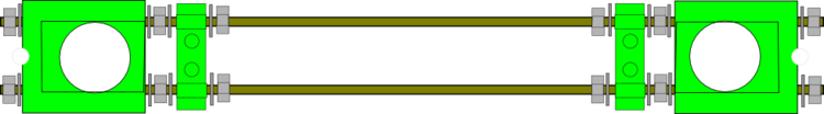
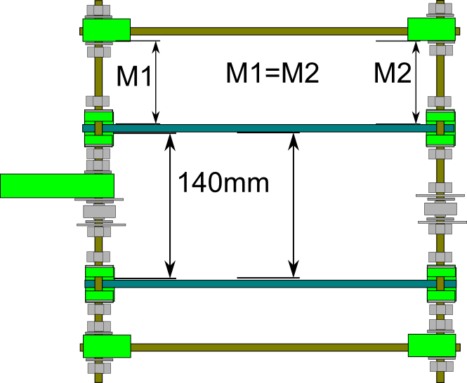
- Slide the two 406mm smooth rods through the bar clamps on the front and rear threaded rods, so that they lie below the threaded rods. They should fit snugly and be approximately parallel.
- Place the narrow side of the print bottom plate between the rods. This ensures they are exactly 140mm (equivalent is 5-33/64") apart from each other. Adjust the nuts on the front side bar clamps until the print bottom plate just barely fits between the rods. Try to get them at an approximately equal distance from the middle of the rod.
- Tighten the front nuts just enough that they do not move on their own, but no further.
- Measure the distance from the left front vertex to the left smooth rod. Adjust the distance from the left rear vertex to the left smooth rod to match it. This ensures the left rod is parallel to the frame. Tighten the nuts on the left rear bar clamp just enough that they do not move around.
- Place the print bottom plate next to the left smooth rod on the rear side. Adjust the right rear bar clamp's nuts until the narrow side of the bottom plate barely fits between the rods.
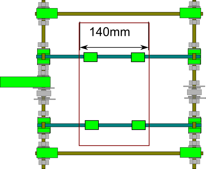
- Recheck the distances from the left vertex to the left rod are the same at the front and rear and that the short side of the print bottom plate fits snugly between the smooth rods both at the front and at the rear. This should ensure that the rods are parallel to each other and to the frame. Use the diagram below to see what it should look like from above.
- Tighten the nuts on all four of the bar clamps now.
- Snap two PLA bushings onto each of the two smooth rods. Make sure they slide freely on the rods, then position them about 120mm apart on each rod, with their top (flat) side facing up. If your bushings are rather stiff, snap them on to one end of a spare length of smooth rod, boil up a fresh mug of water and stand the other end of the rod in the mug until hot. Remove from the mug and slide the bushings down to the hot end. Leave for several minutes and then slide back to the cold end and allow to cool. The bushings should then run more smoothly. (If the bearing are still difficult to move after this technique, it may be necessary to run them up and down along a threaded rod.) Put a dab of glue (Araldite Rapid works well; superglue also works, but doesn't allow for much fine adjustment) on the top side of the bushings. Carefully place the print bottom plate on top of the bushings, so that it's equally far from each of the triangles (see diagram below). Allow the glue to dry.
- While the glue is drying, adjust the position of the bearing on the rear threaded rod until it is exactly aligned with the one on the front threaded rod. Tighten the nuts on the y motor bracket and both bearings at this point. All nuts on the front and rear rods should now be tight.
- Also while the glue is drying, ensure that the hole in the center of the pulley matches the diameter of your motor shaft (it should slide on and fit very snugly). If it is too tight to fit, drill it out. If you find that drilling to 5mm is insufficient to make it fit, and 5.5mm makes it too loose (which it generally will for motors with a 5mm shaft), and a 5.2mm drill bit is too hard to come by, you may find that reaming it with a 5mm allen key will work well, if requiring a bit of manual effort. Alternatively, a needle file can be used to slightly enlarge the hole.
- Insert an M3 nut into the rectangular slot on the base of the pulley. You may need to widen the slot slightly to do this. Make sure that the center of the nut is aligned with the side hole in the pulley that goes to the center hole. Once you are satisfied with the position of the nut, insert an M3 grub screw into the side hole in the pulley. Tighten it until you see the end of the screw inside the center hole, then unscrew it enough to slide the pulley onto the motor shaft. If you find this too difficult, depending on your pulley you may find that the grub screw is able to self tap a sufficiently strong thread into the side hole simply by screwing it in.
- Place the motor with the pulley on it next to the mounting holes in the y motor bracket. Position the motor to the left with the y motor bracket towards you, so that the pulley ends up on the side of the bearing.
- Adjust the pulley position on the shaft so that when the motor is flush with the bracket, the teeth on the pulley are approximately at the position of the bearing.
- Fasten the motor with 3 M3x10 bolts. Put a washer between each bolt and the y motor bracket.
- Recommended: attach the back/bottom of the motor to the bars using zip-ties, kapton tape, picture wire, or any inelastic wrapping. This prevents the Y bracket from flexing with belt tension.
- Tighten the grub screw so that the pulley cannot move along the shaft.
- Position the y belt on top of the print bottom plate and through both of the bearings. Pull lightly on both ends so that it is straight. If the belt is not straight, adjust the position of the rear bearing until it is. Use a marker to mark out the position of the belt on the print bottom plate. Also mark which side of the plate is on the left.
- After the glue has dried, carefully pop the print bottom plate (with the PLA bushings attached) off the rails. Place the two belt clamps perpendicular to the marked position of the belt, several centimeters apart. Make sure the belt position is between the two holes on each clamp. Use a marker to mark where the holes of the belt clamps would be on the plate.
- Carefully drill a 3mm hole through each of the four marked belt clamp holes.
- Place the print bottom plate back on the smooth rods, paying attention to the marking to make sure the correct side is on the left.
- Place one end of the belt, toothed side down, where the holes for the front belt clamp are. Put a washer onto each of two M3x25 bolts, and thread them through the holes in one of the belt clamps. Then attach the clamp to the top of the plate, clamping down the belt. Leave several centimeters of the belt behind the clamp.
- (A 10mm thick print bottom plate is spot on, but if your print bottom plate is 6mm thick, the belt runs about 4mm clear of its top. To get completely parallel running, print two extra belt clamps and position them both under and over the belt. The underneath ones act as spacers.)
- Put two M3 nuts underneath the plate and thread them onto the bolts. Tighten both nuts so that the end of the belt is firmly attached to the plate, toothed side down.
- Pass the belt over the front bearing, around the motor pulley, and then up underneath the plate to the other bearing. Pull it tight, then lay it on top of the plate, toothed side down.
- Put a washer onto each of two M3x25 bolts, and thread them through the holes in the second belt clamp. Then attach the clamp to the top of the plate, clamping down the belt. You can always tighten the belt later with 3 zip-ties: see Tips.
- Attach an M3 nut to each of the two bolts, and pull the belt tight before tightening the two nuts.
- Turn the motor by hand. It should turn with little effort, and each slight rotation should be matched by a slight movement of the plate. You can feel the stepper motor's steps; a single click one way and then a click back again should produce two corresponding movements of the plate. Make sure the plate slides smoothly along the entire length of the rods. Pushing the plate should immediately make the motor turn. Make sure the belt is not too loose (plate and motor should not be able to move independently) or too tight (taking a lot of effort to move the plate). Once you are confident your belt tension is correct, tighten the clamps very firmly. You may now trim the belt, but leave several centimeters behind each clamp for future adjustment.

