Prusa i3 Build Manual
|
English • العربية • български • català • čeština • Deutsch • Ελληνικά • español • فارسی • français • hrvatski • magyar • italiano • română • 日本語 • 한국어 • lietuvių • Nederlands • norsk • polski • português • русский • Türkçe • українська • 中文(中国大陆) • 中文(台灣) • עברית • azərbaycanca • |
Contents
Boxed style Frame Style
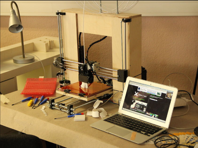
In the future this page might contain a tutorial. Until then, a tutorial for the boxed frame style Prusa i3 by Kliment:
Rods
X Axis;
- 2x 470mm 8mm smooth rod
- 1x 20mm 8mm smooth (for extruder idler, use 8x20 threaded rod or grub screw instead as substitute)
Y Axis:
- 2x 470mm 8mm smooth rod
- 2x 500mm M8 threaded rod
- 4x ~200mm M8 threaded rods
Z Axis:
- 2x 405mm 8mm smooth rod
- 2x ~370mm M5 threaded rod
You could play with the Z lengths to increase building height.
For this you will need longer wood cut for 4 of the 450x100mm plates; add n to both wood (450+n)x100 and all Z axis rod length)
Frame
Default is 15mm thick wood. Get something that is robust!! The thickness is mostly needed because you screw into the side of the wood!
- 6x 450x100x15mm wood
- 1x (450+15)x(100+(15*2))x15mm wood (for the ppl that suck at math; thats 465x130x15mm wood)
Any wood _over_ 15mm thickness will not work for the bottom plate, the Y will then be lifted from the ground.
So if you are using thicker wood for the frame, this _will_ work, but be sure to _NOT_ use thicker wood than 15mm for the bottom plate of the frame.
Single Sheet Frame Style
http://www.flickr.com/photos/prusajr/8107645350/in/photostream
Materials
Parts to be Purchased
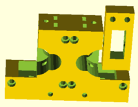
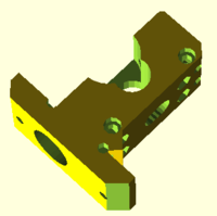
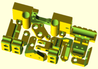
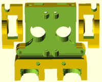
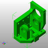
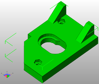
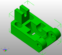
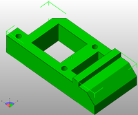
Rapid Prototype Parts
| Description | Qty | Image |
| RP Parts | located in Prusa/single_plate folder | |
| z-axis-top.scad | 1 | |
| z-axis-bottom.scad | 1 | |
| y-motor.scad | 1 | |
| y-idler.scad | 1 | |
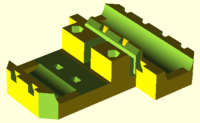
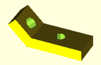
| y-corners.scad | 4 | |
| y-belt-holder.scad | 1 | |
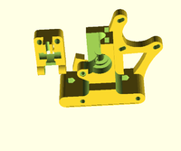
| x-end-motor.scad | 1 | |
| x-end-idler.scad | 1 | |
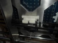
| x-carriage.scad | 1 | |
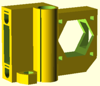
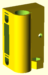
| magnetic-holder.scad (used for hall effect sensors / endstops) | 2 | |
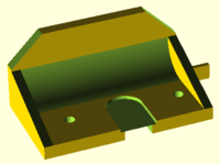
| fan-mount.scad | 1 | |
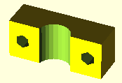
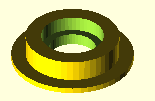
| belt-guide.scad (suit 623 bearing) | 4 | |
| Extruder options | not complete documentation at this stage | |
| gregs-wade.scad (in box_frame/extras folder) | 1 (???) | |
| greg-adapter.scad (in mini/extruder/greg-wade folder) | 1 (???) | |
| dual-extruder.scad (deprecated - experimental) | 1 (???) | |
| compact-extruder.scad (experimental - likely to be replaced by nema17 extruder) | 1 (???) | |
| EiNSTeiN branch | master branch of i3 single-frame parts by EiNSTeiN: master at https://github.com/EiNSTeiN-/Prusa3/ | |
| platter.scad (EiNSTeiN variant) single plate for i3 | 1 | |
| compact-extruder.scad (EiNSTeiN variant) dual extruder in build log images below | 1 | |
| MGS Extruder T2.5 Belts | MGS branch of i3 single-frame parts bySound: i3-unterwelt at https://github.com/alexrj/Prusa3/tree/i3-unterwelt | |
| mgs-body.stl | 1 | |
| mgs-groovemount_ABS.stl | 1 | |
| mgs-idler.stl | 1 | |
| mgs-mount.stl | 1 | |
| x-carriage.stl | 1 | |
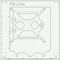
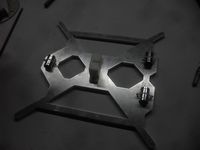
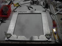
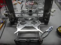
| Single-Frame i3 | Aluminium 6mm plate 370mm x 370mm | |
| Prusa3ALU-FREZOVANY-v4.dxf | 1 |
Note:
The Prusa3 repository (below) includes frames for both aluminum and laser cut wood (sized for 6mm thick) for both the "single_plate" and "mini" variants. The wood frame files include two gussets, which stabilize the frame from flexing. Photos of each can be found at:
"single_plate": http://www.flickr.com/photos/sbgraber/sets/72157632513929965/with/8378333341/
"mini": http://www.flickr.com/photos/sbgraber/sets/72157632518684272/with/8379471692/
The Prusa3ALU-*.dxf and Prusa3WOOD-*.dxf feature y-carriages that use zipties to fasten three LM8UUs to the underside. Prusa3_SC10UU-*.dxf has mount holes for SC10UU linear bearing blocks. Use whichever carriage fits your need.
File Sources
Github:
https://github.com/josefprusa/Prusa3 - Josef Prusa - main development repository
https://github.com/alexrj/Prusa3/tree/i3-unterwelt - Sound MINI repository
https://github.com/EiNSTeiN-/Prusa3/ - EiNSTeiN - 608 bearings, compact dual extruder repository
Other Build Documentation
Single plate build pics: http://www.sub-design.co.uk/i3build/
Build Documentation:
http://78.47.92.212/i3_documentation_pics/
BOM:
http://www.ethercalc.org/wcrkzrngtw
Build Videos:
http://www.youtube.com/watch?v=NixSNAUPciQ
Rod Lengths:
http://titanpad.com/bU77NESnMC
JBFromOZ - notes preparing to build an aluminium frame prusa i3.
Prusa i1/i2 smooth rod lengths should be usable for an i3 single-plate reprap.
Instructions on the github say to RP each part in the single-plate folder. I believe this instruction applies to the box frame version only, some items need more than 1 copy.
Extruder Discussion
It is not yet 100% clear which extruder to use, there is a dual extruder and a compact extruder in the branch though neither looks complete. there is also a Greg's adapter in the /mini/extruder/greg-wade folder, it uses the nuts_and_bolts.scad which needs to be copied to the openscad library folder.
I am planning to use a MGS extruder with a Nema17 stepper, designs from Sound are shown from his i3-unterwelt branch
Build photos from EiNSTieN's build record, including some additional reference to his edits for 608 bearings, GT2 belts, dual extruders etc.
Build Instructions (With Pictures!)
| Description | Image |
| build Y assembly using 4 x corners (RP), 1 x Y motor mount (RP), 1 x Y Idler mount (RP), 4 x M8 threaded rod short 2 x M8 threaded rod long, 2 x M3 x 8mm cap head bolts, (10mm perhaps with M3 washers) 36 x M8 nuts, 36 x M8 washers, 1 x stepper | |
| Clean and de-burr aluminium 6mm plates., tap holes as required | |
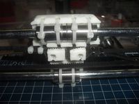
| Cable tie LM8UU's to Y carriage, and attach 1 x Y belt connection (RP), 2 x M3 x 10mm cap head bolts, 2 x M3 washers, 3 x LM8UU bearings 3 x cable ties, 1 x aluminium Y carriage. | |
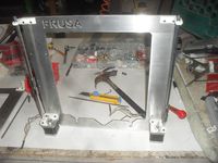
| Attach Z mounts to Aluminium plate. 2 x upper Z mount (RP), 2 x lower Z mount (RP) 10 x M3 x 10mm (mounts to ali plate) | |
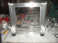
| Attach Z steppers and smooth rods. , 6 x M3 x 8mm Z motor to mounts (10mm with M3 washers). Install LM8UUs into the X Carriage (not onto rods as pictured) | |
| build X carriage and attach to ali plate | |
| attach Y assembly to ali plate | |
| attach and tension Y belt. | |
| Attach and tension X belt. | |
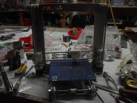
| Attach Heated Bed. | |
| build extruder assembly (dual extruder based on EiNSTeiN's branch as per above in these pictures) | |
| Attach Ramps (standoffs etc as shown) | |
| Complete all wiring! | |
| Attach Extruder | |
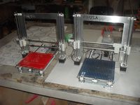
| Dual Printers! | |
| Dual Extrusion! |
Further specific details refer to wiring diagrams and other construction references on this wiki.
