RAMPSSB
|
English • العربية • български • català • čeština • Deutsch • Ελληνικά • español • فارسی • français • hrvatski • magyar • italiano • română • 日本語 • 한국어 • lietuvių • Nederlands • norsk • polski • português • русский • Türkçe • українська • 中文(中国大陆) • 中文(台灣) • עברית • azərbaycanca • |
This page is a development stub. Please enhance this page by adding information, cad files, nice big images, and well structured data!
Release status: Working
| Description | RAMPS Servo Board
|
| License | |
| Author | |
| Contributors | |
| Based-on | |
| Categories | |
| CAD Models | |
| External Link |
Contents
Summary
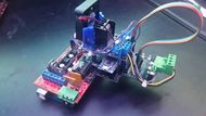
RAMPSSB (RAMPS Servo Board) is a shield that attaches to the AUX1 pins of the common 3D printer control board, RAMPS.
It converts the X and Y stepper motor driver carriers into quadrature encoder closed loop control DC motor drivers. This means that if the carriage gets knocked out of place, it will bring itself back to the same location. No more skipped layers! It also allows RAMPS boards to control things like inkjet printer motion carriages.
Reverse Polarity Warning
Schematic
Layout
Open Source Files
EAGLE, gerber, CAD, and Firmware files can be found here: https://github.com/SZiv/RAMPSSB
Where to get it?
No manufacturers for this yet. ¯\_(ツ)_/¯ The individual parts are easy to find, and everything is through-hole, so its not too hard to make if you have terminals and pin header lying around.
Firmware
The firmware could use some work. While it does work, it is a bit shakey, and while the hardware is stable, the software cannot be trusted with high precision movements at this time. Anyone with control theory expereience is encouraged to work on improving the firmware and if you can make it work better, let me know and I can add it to the official github.
Firmware is uploaded to the Pro Micros individually, and the configuration variables at the beginning should be adapted to your hardware. The inputs are defined by a steps per mm (which is the steps per mm coming out of the RAMPS board). Outputs are defined by counts per revolution and mm per revolution. Counts per revolutions is the number of encoder counts per revolution of the motor shaft). Sometimes, this is listed on the datasheet, but its good to test by attaching the motor encoder, disconnecting the motor power leads, and spinning the motor one revolution. mm per revolutions is the mm of travel per one revolution of the motor shaft. To get this, mark your carriage location, spin the motor 5 revolutions, mark the final location, measure the displacement, and divide it by 5. That should get you close enough to fine tune it with parts.
Firmware on the RAMPS board technically does not need to be modified, but you may need to lower max speed and steps per mm if you are using a high precision encoder (such as a 2000 count per revolution) or else the inturrupts on the encoder will lock up the Arduino
Pin Definitions for the Micro
Direction Input - 1
Step Input - 0
Enable Input - 4
Output Direction 1 - 8
Output Direction 2 - 9
Output PWM - 5
Encoder Input 1 - 2
Encoder Input 2 - 3
Endstop Input - 7
Bill of Materials
| Description | Quantity | Package | Notes |
|---|---|---|---|
| resistor, 200 ohms | 1 | 7mm | LED current limiting resistor |
| LED | 2 | 3mm | LEDs for visualizing PWM outputs |
| L298N DC Motor Driver | 1 | N/A | DC Motor Driver. There are two different versions of these, make sure you get the square version with the screw terminals! |
| 40mm fan | 1 | 40mm | Cooling fan for DC motor driver |
| 20mm M3 Spacers | 3 | N/A | M3 Standoffs for the DC motor driver |
| Misc M3 screws | 5 | N/A | for securing the standoffs to the driver and the fan to the printed bracket. |
| Arduino Pro Micro | 2 | N/A | Developed by Sparkfun, but there are a lot of cheap clones. Necessary because of all of its interrupt pins. |
| Screw Terminals | 1 | 3.5mm | Spare output power terminal. Not strictly necessary. |
| Screw Terminals | 2 | 5mm | Input/output power terminals. |
| 3D printed fan bracket | 1 | N/A | Fan duct for the 40mm fan that connects it to the driver. |
| Male/Female Pin Headers | A lot? ¯\_(ツ)_/¯ | 0.1" spacing. | Buy a couple of Female double rows, male double rows, male single rows, and female single rows. |
| Female-female jumper wires | 20 | 0.1" spacing. | Jumper wires for connecting the DC motor drivers and endstop wires. |
| PCB | 1 | N/A | The Actual PCB. SEEEDstudio sells them for cheap. |


