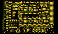
RD3D/1.0
RD3D 1.0
Release status: in development
| Description | RepRap Due 3D Printing shield
Arduino DUE based modular RepRap electronics.
|
| License | |
| Author | |
| Contributors | |
| Based-on | |
| Categories | |
| CAD Models | |
| External Link |
Contents
RD3D v1.0 - Reprap Duet for 3D Printing
This board is derived from Ramps 1.4.2 and has the following features and improvements:
- Suitable for use with Arduino Due: uses 3.3v supply from Due, not 5.0v
- Suitable for up to 24v on both or either Power inputs
- Removed all double Stepper connectors (motors should be wired in series)
- Removed all AUX except I2C, AUX4 (for LCD) and AUX3 (for SPI-Ethernet)
- Removed MAX Endstops
- Removed Thermal Pads to increase power handling capacity between layers
- Added MicroSD Card (for porting RepRapFirmware)
- Moved D8, D9 and D10 LEDs next to their outputs
- Increased current capacity of 3V3 trace to MicroSD, AUX3 and AUX4
- Increased Main Power copper pour (inc. to VMOT) widths, added extra VIAs
- Moved Thermistor jumpers down to end of PCB, linked to closer ADC pins
- Added UA78M08DCY 500mA 8V Power Regulator, to supply Arduino from up to 24v)
- Added extra 6th Stepper Board. Can now do auto-bed levelling (triple Z)
- Added Twin Header for 2 always-on fans (connected directly to Power In)
- Added a SN74HC125 to the MOSFETs to achieve full RDSon (Due is 3.3v)
- Added D11 GPIO (with a pulldown) to disable MOSFETs on Due startup
- Added GND Shielding VIAs
- Significantly adjusted pinouts so that wires do not cross (reduce EMC)
- Simplified Copper pour: single GND on TOP and BOTTOM with low priority
- Fully GPLv3 compliant (full CAD source always available)
Being based on RAMPS 1.4.2 it also has the following features:
- Improved current-carrying capacity (1oz copper instead of 0.5oz)
- Standard removable Blade fuses
- Suppresion capacitors on endstops
- Extra jumper on the reset switch
PCB Design features
Here are some of the design features:
- LEDs next to each power output, Heater, Fans, Extruder
- Improved copper pour for VMOT power
- MicroSD card added; Thermistor terminals moved right next to ADC
- Tri-state Buffer on MOSFETs (3.3v to 5v conversion for Due); D11 disables MOSFETs (defaults to off)
- LDO with an 8V 500mA output supplies power to Due from input voltage, accepts anywhere between 12v and 24v
GPLv3 PCB Board Source code
Available at http://hands.com/~lkcl/rd3d
git clone http://hands.com/~lkcl/rd3d/.git


