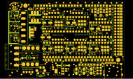
RD3D/1.0
RD3D 1.0
Release status: in development
| Description | RepRap Due 3D Printing shield
Arduino DUE based modular RepRap electronics.
|
| License | |
| Author | |
| Contributors | |
| Based-on | |
| Categories | |
| CAD Models | |
| External Link |
Contents
RD3D v1.0 - Reprap Duet for 3D Printing
This board is derived from Ramps 1.4.2 and has the following features and improvements:
- Suitable for use with Arduino Due: uses 3.3v supply from Due, not 5.0v
- Suitable for up to 24v on both or either Power inputs
- Removed all double Stepper connectors (motors should be wired in series)
- Removed all AUX except I2C, AUX4 (for LCD) and AUX3 (for SPI-Ethernet)
- Removed MAX Endstops
- Removed Thermal Pads to increase power handling capacity between layers
- Added MicroSD Card (for porting RepRapFirmware)
- Moved D8, D9 and D10 LEDs next to their outputs
- Increased current capacity of 3V3 trace to MicroSD, AUX3 and AUX4
- Increased Main Power copper pour (inc. to VMOT) widths, added extra VIAs
- Moved Thermistor jumpers down to end of PCB, linked to closer ADC pins
- Added UA78M08DCY 500mA 8V Power Regulator, to supply Arduino from up to 24v)
- Added extra 6th Stepper Board. Can now do auto-bed levelling (triple Z)
- Added Twin Header for 2 always-on fans (connected directly to Power In)
- Added a SN74HC125 to the MOSFETs to achieve full RDSon (Due is 3.3v)
- Added D11 GPIO (with a pulldown) to disable MOSFETs on Due startup
- Added GND Shielding VIAs
- Significantly adjusted pinouts so that wires do not cross (reduce EMC)
- Simplified Copper pour: single GND on TOP and BOTTOM with low priority
- Fully GPLv3 compliant (full CAD source always available)
Being based on RAMPS 1.4.2 it also has the following features:
- Improved current-carrying capacity (1oz copper instead of 0.5oz)
- Standard removable Blade fuses
- Suppresion capacitors on endstops
- Extra jumper on the reset switch
Design features gallery
Here are some of the design features, with images (in order), below:
- LEDs next to each power output: Heater, Fans, Extruder
- Improved copper pour for VMOT power (includes extra VIAs)
- MicroSD card added; Thermistor terminals moved right next to ADC
- Tri-state Buffer on MOSFETs (3.3v to 5v conversion for Due); D11 disables MOSFETs (defaults to off)
- LDO with an 8V 500mA output supplies power to Due from input voltage, accepts anywhere between 12v and 24v
GPLv3 PCB Board Source code
Full GPLv3 source code is available at http://hands.com/~lkcl/rd3d
git clone http://hands.com/~lkcl/rd3d/.git
BOM, PDFs
- BOM: http://hands.com/~lkcl/rd3d/RD3D_1.0_BOM.html
- Schematic: http://hands.com/~lkcl/rd3d/RD3D_1.0.pdf
- PCB: http://hands.com/~lkcl/rd3d/RD3D_PCB_1.0.pdf


