Recyclebot/pt
|
English • العربية • български • català • čeština • Deutsch • Ελληνικά • español • فارسی • français • hrvatski • magyar • italiano • română • 日本語 • 한국어 • lietuvių • Nederlands • norsk • polski • português • русский • Türkçe • українська • 中文(中国大陆) • 中文(台灣) • עברית • azərbaycanca • |
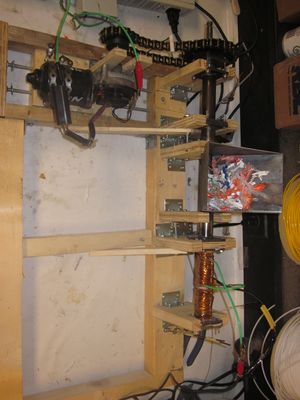
Isto é uma reprodução de Appropedia [1] e [2] criadores do projeto ainda em desenvolvimento. A lista completa das partes metálicas para a v2.2 esta disponivel em Thingiverse. A RecycleBot completa e automatizada está documentada em detalhes para a v2.3. E todos os códigos Arduino funcionais Thingiverse.
Mais Informações no artigo: Christian Baechler, Matthew DeVuono, and Joshua M. Pearce, “Distributed Recycling of Waste Polymer into RepRap Feedstock” Rapid Prototyping Journal, 19(2), pp. 118-125 (2013). Cópia livre e aberta
Seguindo o modelo open source, a RepRap tornou viavel a impressão 3D em pequena escala ajudando tabém a sustentabilidade, como discutido em 3-D Printing of Open Source Appropriate Technologies for Self-Directed Sustainable Development. A matéria-prima plástica da RepRap é uma área onde o custo ainda pode ser reduzido. Aqui uma descrição e análise do projeto para produzir o filamento para RepRap a partir de resíduos de plástico, incluindo propriedades de componentes, procedimentos de ensaio e os resultados de extrusão. O sucesso deste dispositivo irá melhorar ainda mais a acessibilidade da RepRap, reduzindo os custos operacionais. A produção de filamento pode também oferecer uma fonte de renda alternativa. Além disso, permite a reciclagem de plástico em casa. Tendo assim, impacto na gestão de resíduos com a reciclagem em casa, podendo evitar as emissões de gases causadores do efeito de estufa, e em custos económicos associados a programas municipais de reciclagem por "pular" a coleta e transporte dos resíduos.
Contents
História
As informações da primeira Recyclebot estão disponiveis aqui: Recyclebot v1.0. Esta foi uma grande prova de conceito e baseado fora de um projeto de mãos à obra - embora não tenha criado um filamento de qualidade suficiente para ser útil em impressoras 3D.
O Projeto para extrusora de residuos plasticos (Recyclebot v2.0 e v2.1) abaixo, é fortemente influenciada por Web4Deb extruder, que faz a extrusão de HDPE para uso em plantações aquaponicas. Detalhes do projeto Web4Deb pode ser achado no linkWeb4Deb's blog. É parte do Queen's University Mechanical Engineering course, Mech 461 supervised by J.M. Pearce [3], Christian Baechler desenvolveu a Recyclebot v2.0 um dispositivo para converter automaticamente o lixo doméstico de plástico em material para ser usado em máquinas de prototipagem rápida de pequena escala, como a RepRap. Este projeto foi melhorado no grupo - especialmente com a ajuda de Matthew DeVuono.
A Recyclebot v2.2 agora está sendo desenvolvida por Michigan Tech in Open Sustainability Technology Research Group.
Recyclebot v2.0/v2.1
Problema Apresentado
Foi proposto recentemente que as impressoras 3D de código aberto podem ser usadas para impulsionar o desenvolvimento sustentável [4]. Para que isso seja realidade é crítico que os estoques de insumos possam ser desenvolvidos a partir de materiais disponíveis localmente, a fim de evitar a erosão das vantagens de custo sobre a produção local. Utilizando materiais disponíveis localmente, a fabricação open source de tecnologia apropriada (OSAT) não só assegura que a comunidade em questão será menos dependente da ajuda externa, se houver problemas com a tecnologia, mas também cria uma sensação de poder, onde a tecnologia não é entregue como uma forma de dependência, caridade e aprofundamento da ajuda externa. Isto pode ser alcançado através da utilização de matérias-primas para produtos criados a partir de resíduos (por exemplo, sacos de plástico ou garrafas) e através da utilização de materiais locais disponíveis, tais como bio-polímeros. A enorme abundância de plásticos no lixo doméstico (incluindo bolsas, garrafas e embalagens) é uma realidade na maioria das comunidades não-rurais, mas esse desperdício pode ser reutilizado. Um processo pode ser usado para criar a partir de resíduos de plástico, um filamento para uso na RepRap.Sendo assim, uma máquina extrusora de plástico, que aquece o plástico e o extrude como um filamento para poder ser utilizado por impressoras 3-D, é necessário. É notório que a produção de filamentos é um desafio pois, o diâmetro tem de ser preciso e o filamento deve ser extremamente redondo (não oval) ou a extrusora irá produzir peças de qualidade pobre ou ruim como tem sido muitas vezes quando proprietários de RepRaps (Rapman), compram filamento refil localmente. A cuba para a exturora não tem tamanho definido, nem material específico, não ser dependente das propriedades de tamanho do material e avanços, segurança na utilização de uma alimentadora de fragmentos, ou uma picotadora de plastico é uma opção a ser estudada.
Objetivo
O objetivo deste projeto de pesquisa é desenvolver, construir e testar uma extrusora para a RepRap que pode usar resíduos de polímero como matéria-prima
Revisão Literária
Neste link a completa em inglês Extrusor Plastico: Revisão de Literatura. A revisão explora uma gama de literatura sobre tecnologia open source de prototipagem rápida, manipulação de plástico e reciclagem de resíduos, as propriedades dos materiais e tecnologia de extrusão, entre outros.
Public Awareness and Support
Sustainability and 3-D printing both gain significant attention from the public today, and organizations that could help with support and collaboration are already in place. The Perpetual Plastic Project [5] launched by the Better Future Factory [6] design agency is currently working to promote a very similar concept. It seems that their goal is to uncover the lost value plastic waste by turning it into a resource that can be used to create filament and print new products all in one place. This might be an opportunity for RepRap contributors to collaborate with Perpetual Plastic Project, which appears to want to spread its technology.
Design
A description of the design, including detailed assembly instructions can be found below.
Extruder
The design for the waste plastic extruder is heavily influenced by an extruder developed by "Web4Deb" (online username) which extrudes HDPE for use as a growth medium in aquaponics. Details of this design can be found at the Web4Deb's blog and on the device's RepRap wiki page. It was decided that this design would be used as a base and modified to produce 3mm filament for use with the RepRap 3D printer.
The design has the following features. For more information refer to the Assembly Instructions section.
- 3/4" (inner diameter) pipe for extruder barrel.
- divided into 3 individual sections to be assemble together (gearing, hopper and heating).
- 3/4"-17" ship bore auger - inserted in barrel.
- hopper welded to hopper section. Shredded plastic inserted here.
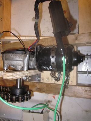
- auger turned using windshield wiper motor (used model from 1994 Dodge Neon)
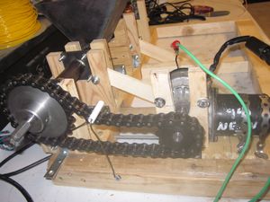
- chain and sprocket drive train, 2:1 ratio (reduces speed, increases torque).
- thrust bearing/washer assembly to constrain movement in the axial direction and counter force applied to the auger when transporting the plastic.
- heating section (described below) and die with 3mm opening.
Heating Section
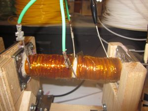
- 14 gauge nichrome wire, coiled around barrel. Secured with heat resistant Kapton tape.
- furnace cement applied to heating section barrel to prevent short circuit. (avoided by using insulated Nichrome).
- reached temperatures of 225oC using 15V, 5A laptop power supply.
- Kapton tape could prevent short circuiting through the barrel, but limited to applications below 250oC. This high temperature is needed if ABS or PET are being extruded.
- Temperature inside the heating barrel tended to lag by about 30oC.
Fourteen gauge wire was chosen in an effort to create the heating zone with minimal power requirements. At present writing, Nichrome wire temperatures of 225oC have been achieved with 75W of power (15V, 5A). Temperature can be adjusted by changing the current passing through the Nichrome wire. Increasing the current increases the wire temperature. Currently the section has only one uniform heating zone, however, provisions were made for two heating zones should more gradual heating of the plastic be found to be beneficial. Many commercial processes use gradual heating to ensure material is evenly heated (Rosato,1997). This website has specifications on the resistance of each gauge of wire and the current required to heat each gauge to various temperature thresholds. Data from this site was used to make initial design calculations.
Presently, the heating section is uninsulated however adding insulation would likely improve performance. Heat up time when the machine is first started could be reduced and higher temperatures could be achieved in the extruder barrel. Fibreglass/kevlar wraps could be used as insulation, as could household fibreglass batting.
Parts Lists
Several further modifications and custom parts are included in the design. A shaft extension was added to the windshield wiper motor to increase the shaft diameter and provide adequate space for mounting of the sprocket. A collar was created to fit between the shaft and gearing section hold the auger in place and allow for the mounting of a thrust bearing. Each of these custom parts is included in the drawings below.
The extruder was constructed with a combination of custom designed and stock materials. Stock materials are summarized in the list below, along with links to their supplier.
Stock Materials:
| |
|
|
| 3/4”x17” Ship bore auger | 1
|
Irwin |
| Nichrome wire, 14 ga. | 1-1/4 lb roll
|
McMaster-Carr |
| Sprockets - Part#: H40B12x1/2 and H40B24 | 2
|
Ringball Corporation |
| Chain - Part#: 40-1R | 2 ft
|
Ringball Corporation |
| Needle thrust bearing and washers - Part #: NTA815 and TRA815 | 1 bearing, 2 washers
|
Koyo |
| 3/4” piping | min. 16”
|
Order online |
| 1/2” sheet metal | 1 sheet, 1ft x 1ft
|
Metals Depot |
| Furnace cement | 100 mL
|
Bomix Pyromix from BMR |
| Alligator clips | 10
|
The Source |
| Corner brackets | 10
|
Local hardware |
| Kapton tape | 1 – 3/8” x 36 yard roll
|
Uline |
| Threaded rods | 2
|
Order online |
| Windshield wiper motor | 1
|
Can buy used, check eBay or others |
| Office shredder | 1
|
Staples |
| Arduino Uno | 1
|
Arduino from RobotShop |
| Arduino compatible USB cable | 1
|
Phidgets, RobotShop |
| Plywood | variable
|
Local hardware |
| Wood | variable
|
Local hardware |
| Fasteners | variable
|
Local hardware |
| Copper wire | 2 ft
|
McMaster-Carr |
All part numbers listed were parts used in the extruder prototypes. Other brands and parts can be substituted. Many of these parts may be available used or as scraps. I found many parts for free, such as the plywood and wooden planks, fasteners and some alligator clips. Those parts listed in italics are materials which would be needed for the extruder body. In my case, these materials were included in the machining costs from the Mechanical and Materials Engineering Machine Shop at Queen's University. Further fabrication is required to prepare the parts for assembly in the extruder. Tools required should be able to cut metal (i.e. grinder, Saws-all, oxy-acetylene torch, etc.) and simple welding. In my case these parts were custom made as explained below.
Custom parts
Custom parts were fabricated in the Queen's University, Department of Mechanical and Materials Machine Shop. Special thanks to Mr. Andy Bryson and his team for their help in fabrication. Most of the parts were manufactured with the use of welding, cutting and drilling equipment. In some cases, a lathe was also required for fabrication. STL files for each of the custom parts can be found below, as well as manufacturing drawings of individual components. The files show the dimensions used for this particular extruder and were chosen based on precedent Web4Deb extruderand to fit other components (i.e. the auger). Optimization of extruder dimensions has not been investigated.
Part Image Files
Assembly Instructions
Below are instructions for the complete assembly of the extruder design that was prototyped for the Mech 461 course:
Main body assembly
The main body consists of:
- heating, hopper and gear section
- 6 x flanges
- die
- bearing support plate
- collar
- thrust bearing and washers
- auger
- large sprocket
Those parts displayed in italics are custom parts. Construction drawings can be found in the parts file section. Most of these parts should be constructable with metal cutting and drilling tools. Their dimensions are those used for the Mech 461 extruder prototype but may be modified to suit individual designs.
Once each part has been constructed. The following procedure was followed:
- A flange was welded to the each end of the heating, hopper and gear sections. This allows for the individual sections to be attached together. Having them in separate sections allows for each section to be worked on separately from the rest of the body. In particular, it is useful to have a separate heating zone which can be worked on separately and insulated from the rest of the extruder assembly. Note: It is likely possible to manufacture the extruder with a single body construction.
- From part 1: You should have a gear, hopper and heating section sub-assembly, consisting of the appropriate piping and 2 flanges each.
- The hopper was welded to the open section of pipe on the hopper zone.
- A plywood square, approximately the size of a flange was cut. It was placed between the hopper and heating sections to reduce heat transfer between the heating zone and the hopper area. The hopper section, heating section and plywood were connected with fasteners through the flange holes.
- The die can be attached to the other end of the heating section using the same method.
- The auger is inserted into the barrel of the extruder.
- The custom collar from above was placed on the shank of the auger. The collar is constrained by the increasing diameter of the auger from the shank to the blade. The smaller outer diameter of the collar is placed closest to the auger blade. It fits inside the extruder barrel. The larger outer diameter constrains auger movement axially toward the heating zone as it is too large to fit in the extruder barrel.
- Next the needle roller thrust bearing and washers were placed on the auger (washer, bearing washer).
- The bearing assembly was constrained with the "bearing support plate." This was connected with fasteners to the flange on the gearing section. The thrust bearing offsets axial force exerted on the auger as it pushes plastic.
- A flat was machined on the auger to provide a better interface with the sprocket's set screw. This was found to be necessary during testing as the sprocket would slip on the shank before the flat was created.
- The large sprocket was placed on the shank and the set screw tightened on the section with the flat.
This completes the assembly of the main extruder body.
Heating Section
The heating section includes the following components:
- heating section sub-assembly (see Main Body Assembly)
- nichrome wire (insulated or unisulated)
- Kapton tape
- copper wire
- alligator clip adaptors
If using uninsulated nichrome:
- furnace cement
The heating zone construction is a fairly simple but important sub-assembly of the waste plastic extruder. The procedure differs slightly if using insulated or uninsulated nichrome wire. If you are using insulated wire, skip step 1 below.
- Cover the heating section barrel (piping) in a thin layer of high temperature resistant cement. I used Bomix Pyromix. Check the components list for a link to the product. Make the layer as thin as possible, but ensure there is no bare metal.
- wrap the Nichrome wire around the barrel from one end to the other. One section covering the whole barrel should sufficient, but two separate heating zones may have advantages (more gradual, even heating; less voltage through any given wire). I used one zone effectively. If you are using uninsulated wire make sure that the coils do not touch or they will short circuit.
- Secure the wire with Kapton tape. Kapton tape is rated to 250oC. If you will be reaching temperatures higher than this (required to extrude ABS and PET) you may want to seal the apparatus with another layer of furnace cement.
- Attach the copper wire to the alligator clips and use these as leads to connect to your power source.
- Test and modify as needed.
I used an old laptop power adaptor (15V 5A) and achieved 225oC. The maximum temperature can be adjusted by changing the current through the wire. This can be done by adding resistance or changing power supplies. Future work is being done to develop a micro-controller system to monitor and control temperature. This has been done in the past on the Web4Deb extruder and for extrusion nozzles in the RepRap 3D printer.
Support Structure
The support structure consists of a wooden base with 8 supports that constrain the extruder body from axial, vertical and torsional movement. The instructions below describe the process used to create the Mech 461 extruder. Much of this design can be modified to meet varying needs. This design has gone through a few evolutions. Increased support was added after one of the wooden supports broke during use. The type and location of supports has also changed. Construction documents for the various supports will be added in the near future.
in progress
Drive-train system
The drive train system consists of the following components:
- large and small sprocket
- windshield wiper motor
- shaft extension (part file available here)
- chain
- tensions device
- 2 x 1/4"-16" threaded rods
- 8 1/4" nuts
- wooden support
- metal strapping
Each of these components are stock components except for the shaft extension which was custom made. The large sprocket was also modified to reduce the inner and outer bore diameters.
Assembly of the drive train system was done using the following procedure. Construction diagrams will be added soon.
in progress
Plastic Grinding
In order for plastic bottles to be converted into viable feedstock using this method, they first had to be ground into small pieces. A number of methods were investigated for this purpose.
Following the work of students at Delft University, a number of common kitchen appliances were tested for their grinding ability [7]. A food processor, coffee grinder and blender were tested, with the blender proving to be the most efficient. In agreement with the Delft U group's work, it was found that the blender worked best when water was added to keep the machine cool and contain the plastic being ground.
This solution was not efficient enough for grinding in large quantities however, as it required too much time. In addition, the ground up plastic had to be dried before it could be used in the extruder. A more efficient method was found by using a Staples(R) brand office shredder which was designed for the shredding of credit cards and compact discs. This proved to be much more time and energy efficient and avoided the use of water. A used shredder was found at a local Value Village for $24.99.
Testing has shown that this method is sufficient. Some problems were encountered with thicker plastic bottles, as the shredder was not able to fully cut them into small pieces. The cutting edge of the auger was still able to handle most of these specimens after they were passed through the shredder. In order to ensure the machine would run smoothly and extrude at a constant rate, scissors were used to cut the largest pieces into smaller bits before they were placed in the hopper.
The full plastic preparation method was as follows:
- washing of plastic bottles
- removal of labels and lids
- cutting into manageable pieces for the shredder
- shredding
Handle and lids were not used as they couldn't be fed through the shredder. The cutting and shredding steps were alternated to ensure that the shredding machine did not overheat as occurred under continuous shredding over a 15 minute period. Intermittent shredding over the course of an hour did not cause any problems with the shredding machine.
Future work should focus on a shredding device which will not require any cutting of the bottles and which can produce smaller plastic chips to be fed to the hopper.
Testing
Testing of extrusion and development of a working 3mm filament feedstock is ongoing. Updates to come.
Future Work
Grinding Device
- creation of a low cost, domestic scale grinding device.
- should grind bottles into small pieces (area < 1 cm2)
- no pre-cutting required
- can accept handles, lids, etc.
See Also Recyclebot info
- Recyclebot at Appropedia
- Open source controller for polymer extruder
- Mechanical testing of polymer components made with the RepRap 3-D printer
- Development and feasibility of applications for the RepRap 3-D printer
- Life cycle analysis of distributed polymer recycling
- Solar powered distributed customized manufacturing
- Waste Reclamation System from PSU
External links
- Adrian Bowyer: Filament Extruder, Granule Extruder Experiments
- Capolight Blog - More Granular HDPE Extruder Experiments
- CNCZone Thread
- Delft - Successful HDPE Extrusion Experiments
- Delft - Final Research Paper
- Fab@Home : Pellet-based Extruder, Research Paper
- Forrest Higgs Post #1
- Forrest Higgs Post #2
- Gingery Books: Gingery's DIY Plastic Injection Molder, Complete Gingery Book List
- Gravity-fed Extruder
- MakerBot Operators List [8],[9],[10],[11],[12]
- MakerBot Operators - All Recycling Threads
- Polymer/Plastic Manufacturing Information
- RecycleBot (HDPE Extruding)


