RepOlaRap
This is still in draft. I'm just putting down my thoughts and plan to edit it as I proceed with my prototyping:
The Polar RepRap, "RepOlaRap", currently only discusses an X+Y axis robot. I plan on attacking a Z axis once I have a working prototype to test the resolution, positioning accuracy and repeatability, and software complexity for the X+Y.
Structural parts from top to bottom:
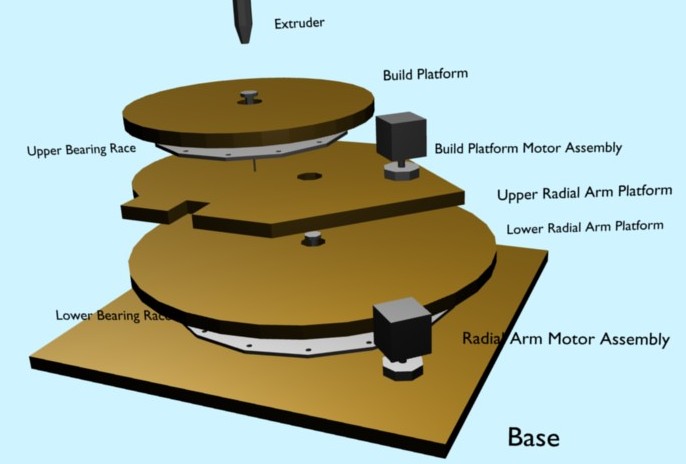
Build platform, 14cm radius disk, 15mm thick
 - Hole + thrust bearing at center.
 - MDF?
 - counter top laminate on bottom for hardness, extending out partially to form belt constraint (?)
 - groove for belt placement around perimeter?
Top Bearing Race, ring, radius: 13cm outer, 8cm inner, 4cm thick.
 - 16x 6mm holes drilled every 22.5 degrees, alternating at 9cm and 12cm radius.
 - 16x 5mm stainless steel balls.
Upper Radial Arm Platform, 15mm thick
 - general shape is a disk 14cm diameter, with an offset half a diagonal square 20cm per side extruded outward.
 - MDF?
 - hole drilled for interface bolt from thrust bearing on Build Platform.
 - counter top laminate on top for hardness on area under bearing race.
 - Three cut outs:
    - Two for encoder device and wiring for absolute radial position of Build Platform.
    - One for radial arm bolt + thrust bearing.
 - Build platform motor assembly will attach to this.
Lower Radial Arm Platform, 21cm radius disk, 15mm thick.
 - Hole + thrust bearing at center.
 - MDF?
 - cemented/glued securely to Upper Radial Arm Platform.
 - One long cutout or groove, 1cm x 9cm, for encoder wiring.
 - counter top laminate on bottom for hardness, extending out partially to form belt constraint (?)
Lower Bearing Race, ring, radius: 16cm outer, 11cm inner, 4cm thick.
 - 16x 6mm holes drilled every 22.5 degrees, alternating at 12cm and 15cm radius.
 - 16x 5mm stainless steel balls.
Base, 46cm x 46cm square, 15mm (19mm?) thick.
 - Hole drilled at center for interface bolt from thrust bearing on Radial Arm Platform.
 - MDF?
 - Cut out for encoder device and wiring for absolute radial position of Radial Arm.
Image illustrating XY platform structure:
My intent to drive the XY platform will use closed form equations for the inverse kinematics done on the host software. I believe that using cubic splines to interpret these kinematics should be adequate to get good resolution, and to reduce communications needs between the host and firmware (Step Spline computations can be done with integer additions and a single shift at the end to get the current stepper position for each time step.)
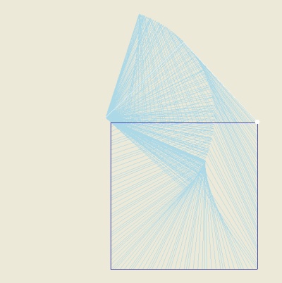
Here is a simulated path for a square from model space (0.05,0.05) - (0.05,1.4) - (1.4,1.4) - (1.4,0.05). Not visible here, there are a few squiffy bits near the center; The simulation sends splines for segments 5mm long, and as you approach the center, this resolution does not allow the spline to reproduce the inverse kinematics accurately enough.

