RepRapPro Mendel wiring/de
| Einleitung | Montage des Rahmens | Montage der Y Achse | Montage der X Achse | Montage der Z Achse | Montage des Heizbettes | Montage des Extruder Vorschubs |
| Hot end Montage | Stromversorgung | Verkabelung | Inbetriebnahme | Drucken | Mehrfarben/Mehr-Material | Mehrfarb Slicer Software | Wartung und Pflege | Fehlersuche | Verbesserungen |
Contents
- 1 Ziel
- 2 Wichtig: Generelle Regeln für die Verkabelung
- 3 Werkzeuge
- 4 Bauteile
- 5 Setting the Motor Currents
- 6 Kabelrouten
- 7 Attaching the control electronics
- 8 The power supply wire
- 9 The heated bed wires
- 10 The X motor wires
- 11 The Y motor wires
- 12 The Z motor wires
- 13 The endstop wires
- 14 The extruder motor wires
- 15 The hot-end ribbon cable
- 16 Connections to the controller board
- 16.1 The power wires
- 16.2 The bed power wires
- 16.3 The X motor wires
- 16.4 The Y motor wires
- 16.5 The Z motor wires
- 16.6 The extruder motor wires
- 16.7 The hot-end heater resistor wires in the hot-end ribbon cable
- 16.8 Unused connector
- 16.9 The X endstop
- 16.10 The Y endstop
- 16.11 The Z endstop
- 16.12 The bed temperature wires
- 16.13 The hot-end temperature wires
- 16.14 The hot-end fan wires
- 17 Testing
- 18 Next step
Ziel
Am Ende dieses Bausabschnitts, ist Ihre Maschine bereit zur Inbetriebnahme.
Sämtliche Kabel der elektrischen Komponenten der Maschine verlaufen zur Controller Platine.
Verlegen Sie diese Kabel entlang des Rahmens von jeder Komponente zum Controller. Lassen Sie großzügig Kabel übrig, wenn der Controller erreicht ist und verbinden Sie die Kabel jetzt noch nicht mit dem Controller.
Erst wenn alle Kabel mit Kabelbindern am Rahmen befestigt sind, werden Sie diese abschneiden und mit dem Controller verbinden.
Sie können die Kabel während Sie diese verlegen direkt mit Kabelbindern befestigen. Wenn ein anderes Kabel auf seinem Weg an der selben Stelle verlegt werden soll, schneiden Sie den ersten Kabelbinder ab und befestigen dann beide Kabel mit einem neuen Kabelbinder. Das ist zwar etwas verschwenderisch aber einfach.
Alternativ halten Sie während des Verlegens alle Kabel temporär mit etwas Krepband. Nachdem alle Kabel verlegt sind, gehen Sie rundherum und ersetzen überall das Krepband durch Kabelbinder. Das ist zwar etwas fummeliger aber dafür sparsam.
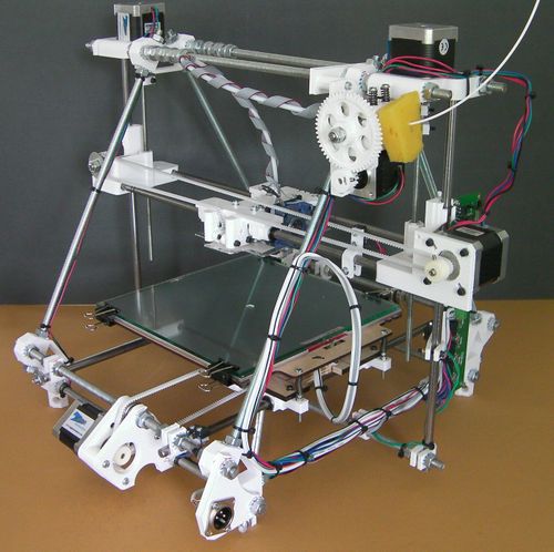
Wenn Sie das unten stehende Bild anklicken, sehen Sie eine hochauflösende Version. Das hilt, Details etwas klarer zu machen.
Wenn Sie bestimmte Kabel identifizieren müssen (und das sind einige), dann können Sie diese mit Tesafilm versehen und mit Filzstift beschriften. Legen Sie das Tesafilm einfach über das Ende des Kabels und beschriften es z.B. mit "X-Endabschalter" (oder was auch immer). Nachdem alles verkabelt und getestet ist, können Sie diese später entweder entfernen oder Sie lassen sie einfach dran. Das erleichtert Ihnen die Arbeit, wenn Sie die Maschine später wieder zerlegen wollen.
Stellenweise hilfreich kann es sein, wenn Sie die 5 Sets der vier Motorkabel an deren Ende mit Klebeband zusammenkleben und beschriften. Das hilft, Verschlingungen während des Verlegens zu vermeiden und Sie können die Kabel einfacher identifizieren, wenn Sie diese am Controller anschließen.
Wichtig: Generelle Regeln für die Verkabelung
Sie zerstören einen Großteil Ihrer RepRap Elektronik, wenn Sie die Verorgungsspannung verpolen. Eine andere zerstörerische Ursache ist das kurzschließen von hochstromigen Komponenten wie der Motoren oder Heizwiderstände und das verbinden von Hochspannungs-komponenten, wie den Schrittmotoren mit Signaleingängen wie z.B. den Temperatursensoren.
Also - In den Abschnitten weiter unten wo Ihnen gesagt wird, Dinge zu überprüfen - Bitte prüfen Sie diese sorgfältig. Den Mehraufwand ist es auf jeden Fall wert.
Auch sehr wichtig für die nachfolgenden Schritte: Wenn Sie Kabel mit Schrauben befestigen, isolieren Sie diese etwa 5mm ab, verdrillen die Kabel zwischen Ihren Fingern und vezinnen diese mit Lötzinn. Das verzinnen ist notwendig für einen guten Kontakt und stellt sicher, daß nicht einzelne Litzdrähtchen abstehen und dadurch Kurzschlüsse verursachen.
Wenn Kabel eine Komponente verlassen (wie z.B. Motoren) oder ein Gerät erreichen (wie z.B. Schraubverbindungen), lassen Sie ein kleines Stück des Kabels in einer kleinen Schleife hängen (ca. 20mm) - Ziehen Sie die Kabel nicht straff.
Abschließend noch der Hinweis, wenn Sie irgendwelche Änderungen an der Verkabelung oder anderen elektrischen Bestandteilen der Maschine vornehmen, Trennen Sie zuerst sowohl die Stromzufuhr als auch die USB Verbindung.
Werkzeuge
- Abisolierzange
- Multimeter
- Lötkolben
- Kleine Schraubendreher
- Schraubstock
Sie benötigen außerdem eine Rolle Tesafilm.
Bauteile
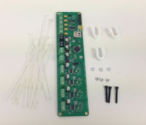
| |
| Bauteile | Menge |
| Controller Platine | 1 |
| Hochstromkabel | 0.5m |
| gedruckte U Klipse | 3 |
| M3 x 25mm Schrauben | 3 |
| M3 Muttern | 3 |
| M3 Unterlegscheiben | 6 |
| Plastikschlauch mit 3mm Innendurchmesser | 20mm |
| Kabelbinder | etwa 60 |
Setting the Motor Currents
If you have purchased a machine from RepRapPro, this is already been done for you. If not, or if they need adjusting for any reason, this process is described here
Kabelrouten
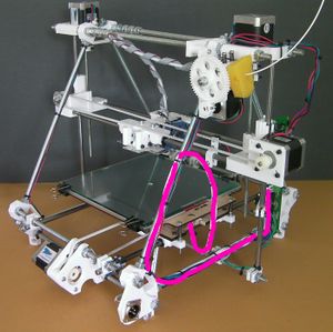
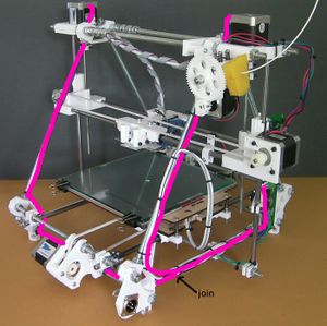
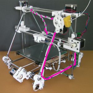
In what follows you will find the routes of the individual connections superimposed on this picture. It is taken from the back of the machine, and the side of the machine on the picture's right is therefore the left side of the machine when it is viewed from the front in its normal working position.
Almost all the wiring runs down the triangle threaded rod to the fore of the picture, and then along the triangle threaded rod at the bottom.
Attaching the control electronics
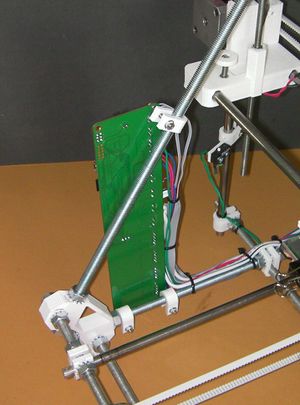
Attach the three U clips to the frame as shown. The controller board goes on the left hand side of the machine at the front (that is, the side of the frame that is on the same side as the XLR power input connector, but at the other end).
Using a sharp blade cut the 3mm internal-diameter plastic tube into three pieces of equal length of about 7mm. These will form spacers between the printed circuit board (PCB) of the controller and the U clips.
Adjust the positions of the U clips so that they line up with the holes in the PCB and the PCB is vertical.
Attach the board to the clips with the screws, washers and nuts. The order goes:
- screw head
- washer
- PCB
- 7mm plastic tube
- U clip
- washer
- nut
Facing the machine from the front, the components on the PCB should be away from the triangle frame and the USB connector and SD card holder should be at the top of the PCB pointing to the front.
The power supply wire
Read through all of this section before starting work on it.
Detach the XLR plug from the frame vertex at the back.
In what follows take great care that there are NO filaments of wire that are sticking out from twisted bundles. These can cause shorts.
Then, if you are building the single-colour version of Mendel, do this:
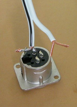
Bare the high-current wire ends, and split each end in two equal halves. Twist those halves separately.
Solder the two from the wire with the black stripe (the Ground - GND wire) to Pin 1 and the plug shell tab.
Solder the two from the plain wire (the +12 volt wire) to Pins 2 and 3.
The pin numbers are embossed on the plug. The picture shows the GND connections made, and the +12 volt connections about to be made. The unsoldered fork in the picture going to Pins 2 and 3 is shown a little long; the bared wires need to be about 2/3 the length shown.
Trim the excess wire from the tab with side cutters.
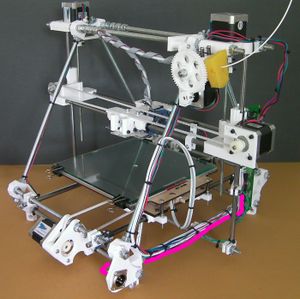
Fit the XLR plug back in the machine. The picture above shows the route of the power wire coloured cerise. Leave a small loop at the XLR plug free for strain relief. Attach it with tape or cable clips to the bottom rung of the triangle, but leave the controller board end free for the moment.
If you are building the single-colour version of Mendel skip to the next section.
If you are building the multi-material/multi-colour Mendel you need two power cables, not one:
The one going to the master controller board is 600mm long, and you will need another for the slave controller that is 1m long. Wire one pair into Pins 1 and 2, and the other to the tab and Pin 3. Then short Pin 1 and the tab, and Pins 2 and 3 with two small pieces of thick wire.
Fit the XLR plug back in the machine and run the shorter wire as described above. Run the longer wire along the bottom bar at the back of the machine and forwards along the opposite side to the master controller. Make sure that the two ends of this wire are separated. Wrap a little tape round them to insulate them temporarily.
The heated bed wires
Bare the ends of the two thin wires from the bed (the thermistor wires) and use your meter to check the resistance between them. It should be about 10K ohms (though this will depend on room temperature).
Push the meter probes in the ends of the thick wires (the bed heater PCB). The resistance should be about 1.5 ohms.
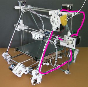
Run the power wire and the thermistor signal wire from the heated bed along the route shown. Cable-tie the two together where they loop free in the air. As you can see, the loop joins the frame about half way up.
Check that the bed of the machine can run freely from one Y extreme to the other without the wires pulling taught and without their catching on anything (particularly the M5 screw that drives the Z axis).
Again, don't attach the wires to the controller for the moment.
The X motor wires
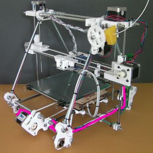
Run the X motor wires along the route shown. (The little bit of cerise colour along the X axis is for the X endstop. That will be done later.)
Leave a generous loop in free air. Remember that the Z axis has to be able to move up and down its full length.
Don't attach the wires to the controller.
The Y motor wires
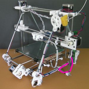
Run the Y motor wires along the route shown. They attach to the bottom threaded rod of the frame at the back. (The little bit of cerise by the Y endstop switch is the wire for that. That will be done in a minute.)
Again, don't attach the wires to the controller.
The Z motor wires
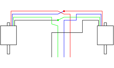
The two Z motors are wired in series as shown in the diagram above. It doesn't matter which motor in the diagram is the left one and which the right - the result will be the same.
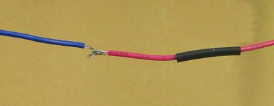
Run the Z motor wires along the routes shown. Make the joins where indicated.
To make the join bare about 10mm of each wire. Put a short length of heatshrink on one. Form each end into a V (blue wire), hook them together, and then close the Vs (red wire). Solder the join (with the heatshrink further away than shown - you don't want to shrink it prematurely).
Move the heatshrink over the join and shrink it with the hot barrel of the soldering iron (don't use the tip - that will make a mess of solder on the outside of the heatshrink.)
Don't attach the wires to the controller.
The endstop wires
Cut the ends off the motor wires at the controller board end. Make sure you leave a generous length on each to connect to the controller. If you taped and labelled you motor wires, put new labels just on the motor sides of the cuts before you make them.
Connect your endstops using two wires each. It is a good idea to use a different colour for each axis as this will make it easier to get the endstops connected to the correct input. You should now have plenty of multi-colour wires trimmed from the stepper motors.
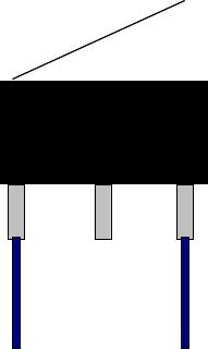
The diagram shows a switch with a lever. RepRapPro Mendel works equally well with levered and un-levered microswitches.
You will probably find it easiest to connect the wires to the endstops with them removed from the machine. Unscrew the three h-shaped clips.
For each endstop switch, crimp or solder a terminal onto the end of the wires, then cover with some heatshrink to insulate the terminal. Connect to the outer pins of the limit switches (the NC = Normally Closed connections; RepRap expects the switch to open when the endstop is hit.)
Put the endstops and their h clips back on the machine.
The X endstop wires
The X endstop wires run along the same path as the X motor wires.
Leave a reasonable loop between the switch and the frame - you may want to adjust the position of the X endstop.
Cable clip all the wires together where they loop free in the air. Get all wires in the loop the same length for neatness (Hint: don't pull the cable ties fully tight. Then you can slide the wires through them to get everything neat before tightening.)
Don't attach the wires to the controller.
The Y endstop wires
The Y endstop wires run along the last part of the route of the Y motor wires.
Don't attach the wires to the controller.
The Z endstop wires
The Z endstop wires run along the route shown. Leave a good loop from the switch to the point where it first connects with the frame. You will need to adjust the height of the switch.
Don't attach the wires to the controller.
The extruder motor wires
If you are building the multi-material/multi-colour version of Mendel skip to the Connections to the controller board Section below.
Run the extruder motor wires along the route shown.
Don't attach the wires to the controller.
The hot-end ribbon cable
The hot-end ribbon cable should already be loosely wound round the PTFE filament feed tube.
Attach it to the frame along the route shown.
Don't attach the wires to the controller.
Connections to the controller board
First make sure that all the moving parts of the machine can move freely for their full travel without fouling or snagging any of the wiring.
If you have attached all the wires with tape, now is the time to go round the machine cutting off the tape (don't cut the wires...) and attaching the wires permanently with cable ties.
What you are going to do is to trim the wires to length, twist them, tin them, and attach them to the appropriate screw connector. When a wire is in its connector the insulation should abut (but not enter) the metal part of the connector. There should be no bare wire visible.
When you twist and tin the ends of the wires, put them in their connector to check the length. If any are a little long, trim them with side cutters.
When you tighten the screws in the controller board's connectors take care that
- Your screwdriver doesn't slip and damage the board,
- You don't put excessive twist stress on the board or push against it too hard - support it with your free hand.
The power wires
If you are building the multi-material/multi-colour version of Mendel skip this section. The power wires will be connected later.
Before you connect these, check the wires' polarity. Separate about 30mm of the end of the two power wires (don't get the bed wires by mistake).
Set your meter to read voltage. Connect the power supply into the XLR plug on the frame and plug in the mains cable, but don't turn it on.
Put the COM or Ground probe of your meter on the copper at the end of the wire with the black stripe. Put the Volts-Amps-Ohms probe on the copper in the plain wire.
Turn on the mains. Your meter should read about +12 volts. If it reads 0 or -12 volts, you have made a mistake - find it and fix it.
Turn off and disconnect the power supply.
Cut the wires to length so that they will reach the power connector on the board. The GNG (black stripe) wire goes to the top of the connector and will have to be a little longer.
Bare then ends of the wires and twist them tight. Tin them. Don't use too much solder, or the result will be too fat to fit in the connector.
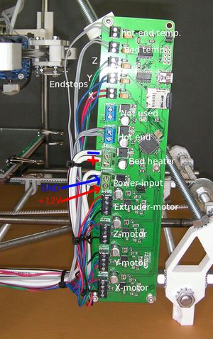
Screw the wires into the power connector. As mentioned the GND wire with the black stripe goes to the top, the plain wire to the bottom.
Don't do the power connector up tight - you are going to have to connect something else to the same connector in a minute.
This is the single most important electrical connection in the machine. If you get it wrong expensive bad things will happen. Take a moment to double check it.
The bed power wires
These go to the connector just above the power input connector. Again the black stripe is the low voltage one and goes to the top. The plain wire is the +12 volts wire and goes to the bottom.
Connect the wires in exactly the same way as the power wires.
The X motor wires
These go to the bottom connector. From the bottom upwards the sequence is Black, Green, Blue, Red.
The Y motor wires
These go to the connector above the X motor connector. From the bottom upwards the sequence is Red, Blue, Green, Black (that is, the opposite of X; remember that it is the Y carriage that moves, whereas X and Z move the head; therefore Y needs to turn backwards).
The Z motor wires
These go to the connector above the Y motor connector. From the bottom upwards the sequence is Black, Green, Blue, Red (that is, the same as X).
The extruder motor wires
If you are building the multi-material/multi-colour version of Mendel, skip this section.
These go to the connector above the Z motor connector. From the bottom upwards the sequence is Black, Green, Blue, Red (that is, the same as X).
The hot-end heater resistor wires in the hot-end ribbon cable
If you are building the multi-material/multi-colour version of Mendel, skip this section.
A reminder from when you wired the hot end: the wires across the ribbon cable in order go like this:
- Wire with the colour stripe: Thermistor
- Thermistor
- Fan + volts
- Fan ground
- Heater resistor wire 1
- Heater resistor wire 1
- Heater resistor wire 2
- Heater resistor wire 2
The hot-end heater resistor wires come in pairs - you will remember that you connected two to each end of the resistor to get a good current carrying capacity.
The hot-end heater resistor wires go to the connector above the bed power wires.
Split them off from the hot-end ribbon cable, bare the ends, twist the pairs together, tin them, and fit them in the connector. The polarity doesn't matter - you can connect them either way round.
Unused connector
The connector above the hot-end heater resistor wire connector is not used.
The X endstop
The X endstop wires connect to the connector above the unused connector. The polarity doesn't matter - you can connect them either way round.
The Y endstop
The Y endstop wires connect to the connector above the X endstop connector. The polarity doesn't matter - you can connect them either way round.
The Z endstop
The Z endstop wires connect to the connector above the Y endstop connector. The polarity doesn't matter - you can connect them either way round.
The bed temperature wires
The wires that run along with the bed power wires connect the bed's temperature-measuring thermistor. They connect to the connector above the Z endstop connector. The polarity doesn't matter - you can connect them either way round.
The hot-end temperature wires
If you are building the multi-material/multi-colour version of Mendel, skip this section.
There are two wires from the hot-end ribbon cable that connect the hot-end temperature-measuring thermistor. They connect to the connector above the bed temperature connector. The polarity doesn't matter - you can connect them either way round.
The hot-end fan wires
The hot-end fan wires in the hot-end ribbon cable do not connect to the terminals marked "fan" - they are for optional additional cooling.
The hot-end fan wires connect to the power connector in parallel with the power input - the hot-end fan is on all the time.
Make sure you get the polarity right. You should have marked the fan's + and - connections when you wired up the fan. Trace them through by counting wires across the ribbon cable.
Slacken the power wire screws and connect the fan wires in parallel with the power.
Tighten these screws firmly - this connector has to carry a large current.
Never operate your RepRap without the fan connected and running. The extruder needs the cooling at all times.
Testing
Set your meter to measure resistance. Short the probe ends. You may find (particularly if your meter is not the most expensive one on the market) that the reading is not quite 0 ohms. Note down what it is - this is your meter's idea of a dead short. Add this number to the low resistances given below.
Put one probe on the casing of the XLR power connector. Put the other on the cover of the SD card socket. The meter should read 0 ohms.
Now the most important check: plug the power supply into your RepRap and put the mains wire on the power supply, but don't connect it to a mains socket. Measure the resistance between the earth pin on the mains plug and the cover of the SD card socket. The meter should read 0 ohms, or at most a small fraction of an ohm. If it doesn't, you have made a mistake. Find it and fix it before you do anything else.
Measure the resistance between the two screws on the power connector. This may start low and then rise. (This is the capacitors in the circuit charging up with the tiny current from the meter.) It should level out at a few hundred ohms.
Measure the resistance between the two screws on the bed power connector. This should be about 1.5 ohms.
Measure the resistance between the two screws on the hot-end heater resistor connector. This should be about 3 ohms.
Make sure all the moving axes are not touching their endstop switches. Check that each resistance on the X, Y and Z endstop connectors is 0 ohms. That is to say the endstop switches should be closed. Press each switch in turn. The corresponding resistance should rise to about 6K ohms (the resistance of the circuit components on the controller board in parallel with the switch).
Check the heated bed temperature sensor connector. The resistance should be about 5 kilohms. This is not just the resistance of the sensor. Other parts of the circuit on the controller board are in parallel with it.
If you are building the single-material/single-colour Mendel, check the hot-end temperature sensor connector. The resistance should be about 10 kilohms. This is not just the resistance of the sensor. Other parts of the circuit on the controller board are in parallel with it.
Measure the resistance between Pin 3 on the XLR connector and the +12 volts input screw on the controller board. This should be 0 ohms.
You did set the motor currents, as described at the top of this page, didn't you?
