RepRapPro Setting Motor Currents
Contents
Introduction
There are four small potentiometers on the Melzi PCB. These set the current (Amps) that the stepper motor driver chips on the PCB will send to the stepper motors.
It is very important to set these correctly, as the Melzi PCB is deliberately designed to be able to drive bigger motors than most RepRaps use (to allow for upgrades and enhancements). This means that it is possible to set the currents too high, which will damage the motors, and possibly the Melzi PCB.
The wiper on each potentiometer generates a DC voltage that is sent to the chip. This is the reference voltage; it defines how much current the stepping motor driver chip supplies to the motor. The bigger the reference voltage (VREF), the higher the current (A) that the chip will send to the motor. For most NEMA14 motors, the current maximum is 1A, but this will generally cause it to get warm, so a setting of 750mA is recommended. For NEMA17 motors, depending on size, the limit on current is generally between 1.3A and 1.7A. If you drive stepper motors with more current than they were designed for, the motor will get hot, and may be damaged.
The stepper driver chip also has a limit on output; if you set the reference voltage too high, the chip will overheat and shut down (the chips have overheat and overcurrent protection). Generally, the stepper driver chip is limited to around 1.25A, due to overheating. This should be plenty to power all NEMA14 and NEMA17 motors, and move the axes on a RepRap.
Identify your Melzi
Different versions of the Melzi use different 'sense' resistors; these effect the voltage you need to set, to get the motor current you want. To identify the version of your Melzi, see this page Melzi. The sense resistors (RS) are the pair of resistors between the stepper driver chip and the motor screw terminals, and typically have a value of either 0.05 ohms and 0.1 ohms.
To calculate the required reference voltage for a desired current, use the formula:
current (A) = reference voltage (VREF) / (8 * sense resistor (RS) )
or, rearranged:
reference voltage (VREF) = current (A) * 8 * sense resistor (RS)
Melzi V1 settings
The Melzi V1 and the 'Melzi 1.0/2.0 eBay Hybrid' usually have sense resistors of 0.05 ohms. To supply 1A to the motors, set the reference voltage on the potentiometer to 0.4V.
0.4V / (8 * 0.05) = 1A
For NEMA14 motors (Huxley axis motors and older Mendel/Huxley extruder drives), set the reference voltage to 0.3V (750mA), up to a maximum of 0.4V (1A).
For NEMA17 motors (Mendel axis motors and current Mendel/Huxley extruder drives), set the reference voltage between 0.3V (750mA) to 0.4V (1A), up to a maximum of 0.5V (1.25A).
Melzi V2 settings
The Melzi V2 should have sense resistors of 0.1 ohms. RepRapPro have been supplying the Melzi V2 board since Summer 2012.
Beware! Many boards sold online as 'Melzi V2' are NOT V2! The Melzi V2 uses A4982 stepper driver chips (rather than A4988 stepper driver chips on Melzi V1), and has other improvements over the Melzi V1. If in doubt, check the value of the sense resistors, between the stepper driver chip and the . If still in doubt, set the reference voltage low (0.4V), and slowly increase.
To supply 1A to the motors, set the reference voltage on the potentiometer to 0.8V.
0.8V / (8 * 0.1) = 1A
For NEMA14 motors (Huxley axis motors and older Mendel/Huxley extruder drives), set the reference voltage between 0.4V (500mA) and 0.6V (750mA), up to a maximum of 0.8V (1A).
For NEMA17 motors (Mendel axis motors and current Mendel/Huxley extruder drives), set the reference voltage between 0.6V (750mA) to 0.8V (1A), up to a maximum of 1V (1.25A).
Generally, RepRapPro supply Melzi V2 boards, for Huxley and Mendel, with the reference voltage set to 0.6V for 750mA.
Setting the motor currents
Make sure you are working on an insulating surface and that nothing that conducts electricity can touch any part of the Melzi PCB.
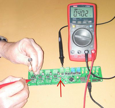
Start by putting the jumper (red arrow) across the two pins closest to you in the picture. This will power all the logic of the Melzi from the USB.
Set your meter to read volts, and connect it's negative/common wire to the negative power screw terminal on the Melzi. Screw it in securely, but don't over-tighten it.
Plug your Melzi into your computer using its USB cable. The Melzi's LED should come on.
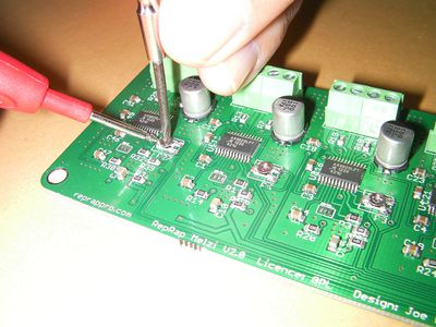
Put the other meter probe (+ volts) on the single solder tab at the left of each potentiometer. Take very great care not to short to any other connection or component with the probe. You may have to stab the connection quite hard to get a reading - the soldering of the board can coat the solder with a thin insulating layer of flux.
Use a small screwdriver to turn the potentiometer until the meter reads 0.8 volts (for example - see above for voltage for particular motors). This doesn't have to be accurate to 10 decimals - somewhere between 0.79 and 0.81 volts is fine.
Do this for each of the four potentiometers in turn.
The vast majority of potentiometers increase the voltage by turning clockwise. But a tiny few work backwards... Note down which way you need to turn the pots to increase the voltage. You may need that information later.
When you have finished disconnect the USB, and then remove the screwed-in meter connection.
If you are building a multi-material/multi-colour RepRap then repeat the above current setting steps for the second slave controller board. Then put that to one side for later.
Technical note on how the currents are regulated
You don't need to know this, but it is interesting...
The stepping motors are powered at 12 volts (Mendel) or 19 volts (Huxley). If you measure the resistance of one of the motor's coils, you will find that they are around 3 ohms. This implies a current of 4A if you were to drive them from, say, 12V, which is far too much. We need 1 A.
The driver chip could regulate the 12V down to 3V to get that correct current of 1A. But then it would be dissipating 9V x 1A x 2coils = 18 watts. That's soldering-iron power, and the chip would fry.
So what it does instead is to use pulse-width modulation (PWM): it sends an ultrasonic square wave to the motor and varies its mark-space ratio to give an average current of 1A. The MOSFETs in the chip are then either fully off (high voltage but zero current, so no power dissipation at all) or fully on (high current, but very low voltage, so very small power dissipation). That way the chips stay at a sensible temperature. When your RepRap is working properly they should be around 10 oC above ambient.
The chips can then also do clever things with the PWM to energise the coils in smoothly varying proportions. They do this to give you microstepping. The motors have 200 steps per revolution, but the driver chips can cause them to 'hang' part-way between two poles to position the rotation much more precisely than 1/200 of a revolution. This both gives much finer resolution, and much less jerky movement.
Why, you may wonder, not use motors with a higher resistance to avoid all this fancy footwork needed from the controller chips? The answer is that fine control - the chips can sense the instantaneous current that the motors are drawing, and also the back EMF that they generate when they move. Because they have lots of drive current to spare and are driving a low resistance, they can do clever tricks to overcome the delays that would otherwise be caused by such things as the motor's inductances. If you examine the actual signal that the driver chips send down the wires to the motors on an oscilloscope you will see that it is very complicated indeed.
This complexity means that you can't realistically measure the motor currents using - say - a simple meter. But you can set the control voltage going into the chips that decides its average. That is what you did above.
You will see throughout these instructions that we go on and on about disconnecting the power before changing any wiring. This is incredibly important, especially given the way the stepper motors are controlled as just described. As you can now imagine, if you disconnect a stepper motor wire while the motor driver chip is powered up, the chip sees the current fall to zero, so it compensates to increase the current. But it's well nigh impossible to disconnect any mechanical connector cleanly - the contacts always make and break as the wire is sliding. So when a break becomes a make the chip is trying to drive the motor at full blast, with the result that one or both of them will go BANG!, then never talk to you again...

