RepRapPro Tricolour z axis assembly
Introduction | Frame assembly | Y axis assembly | X axis assembly | Z axis assembly | Heated bed assembly | Extruder drive assembly | Hot end assembly | Wiring | Power supply | Commissioning | Printing | Multi‑colour/multi‑materials | Colour Printing - Slic3r | Colour Printing - RepRapPro Slicer | Maintenance | Troubleshooting | Improvements
| A notice about these instructions! |
|
These instructions are open to editing by everyone and anyone. |
Goal
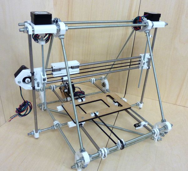
By the end of the stage your machine should look like this:
Tools
You will need the following tools
- M3 Allen key
- Long-nosed pliers
- Tweezers
Step 1: X carriage assembly
The Carriage
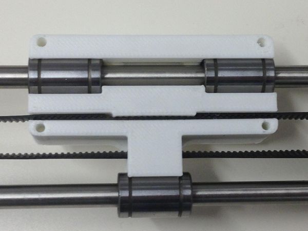
Next fit the belt to your X axis. Take the remaining belt, and insert the free end into the slot in the right end of the X carriage so that it locks with the teeth of the small length of belt. It should ideally be placed as far into the slot as possible so that the end touches the edge of the narrow gap in the centre of the carriage. Then feed the belt through the X end Idler, around the small bearing, back through the carriage, around the motor pulley and back into the slot on the X carriage as shown below


