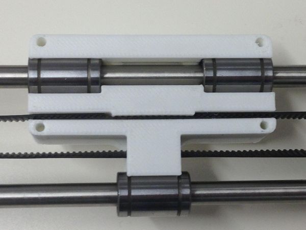
RepRapPro Tricolour z axis assembly
Introduction | Frame assembly | Y axis assembly | X axis assembly | Z axis assembly | Heated bed assembly | Extruder drive assembly | Hot end assembly | Wiring | Power supply | Commissioning | Printing | Multi‑colour/multi‑materials | Colour Printing - Slic3r | Colour Printing - RepRapPro Slicer | Maintenance | Troubleshooting | Improvements
| A notice about these instructions! |
|
These instructions are open to editing by everyone and anyone. |
Contents
Goal
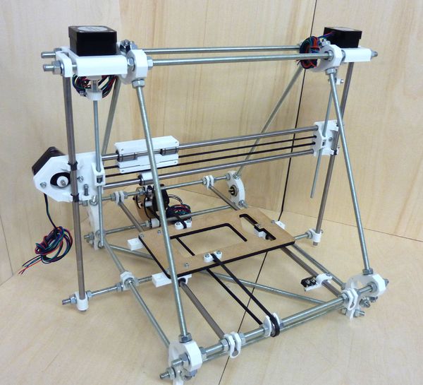
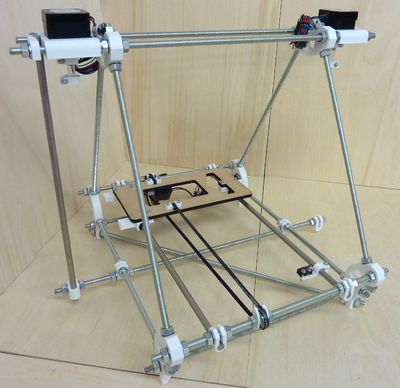
By the end of the stage your machine should look like this:
Tools
You will need the following tools
- M3 Allen key
- Long-nosed pliers
- Tweezers
Step 1: Z Coupling
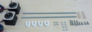
| |
| Item | Quantity |
| Nema 17 Motor | 2 |
| Printed coupling | 4 |
| 30mm 5mm Diameter tubing | 2 |
| M3 Washer | 8 |
| M3 Nut | 4 |
| M3x20mm cap screws | 4 |
| M3x10mm cap screws | 4 |
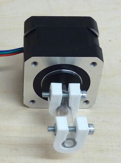
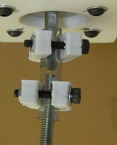
Start by fitting the couplings to the Z Motor. Inserting half of the tubing over the motor shaft. Next take one of the printed couplings and clip it over the motor side of the tubing as shown. Ensure that the gap in the coupling is aligned with the flat of the motor shaft. Then insert one of the M3 X 20mm cap screws and a washer into the hole in the coupling, and secure with a nut on the other side. Repeat this setup on the free side of the tubing; however leave the clamps on the free side loose.
Repeat this setup for the second Nema 17, and mount each of these motors to the Z motor mounts at the top of the frame using the 2x M3x10mm cap screws and washers on each.
Step 2: Z Drive

| |
| Item | Quantity |
| M5 Nuts | 2 |
| 15x7mm Spring | 2 |
| 8mm Igus Clip Bushing | 4 |
| 215mm M5 Studding | 2 |
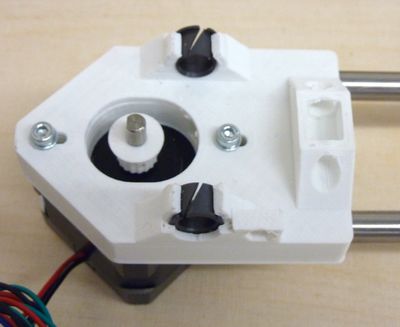
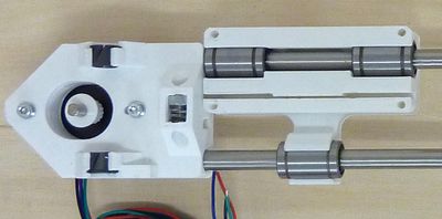
Begin by insert the clip bushings into the X ends. You can curl them up so their ends overlap to insert them. Be careful. Check their internal diameter by running one of the 8mm rods down them. If the rod is too tight (don't force it), use a small needle file to remove a small amount of material from the bushing holders. Alternatively put a 9.5mm drill bit shank in a vice, take the bearing inserts out, and slide the printed part over the drill to clean out the hole. Again be careful - you don't want to remove too much material and make a sloppy fit.
Repeat this process until the rod just fits and slides smoothly. It should not wobble from side to side.
Next insert a spring and an M5 nut into the slots within the X ends. The nut should be placed at the top of the trap (the side with two linear bearings) with spring underneath as shown:
Next thread the M5 studding into the nuts in the X end. Try to thread them in evenly such that the bracket is roughly half way along each piece of studding. Loosen the Z bar clamps just enough so that you can partially slide the bars out. Do not slacken them off alot as your machine has already been squared and will require realignment other wise. Next insert the smooth rod on the side of the machine with two linear bearings in Y through the X motor mount clip bearings and retighten its bar clamp.
At this point the X end idler needs adjustment to ensure its clip bearings align with its Z bar. Begin by offering up its smooth rod to the clip bearing. At this stage you should find the idler bracket needs adjusting outwards to correct the alignment. Tighten the adjustment cap screws in the end of idler bracket accordingly, and slide the smooth rod into its clamp and retighten.
Finally for this step use a rectangular object to support the X carriage on the Y Frog. Then screw the ends of the M5 rods into the plastic tubes on the motors.
Have gaps of about 2mm to 3mm between the tops of the M5 rods and the bottoms of the motor shafts. (You can see this because the poly tube is transparent.)
Tighten the U clamps on the motor shafts and the M5 rods. Remember to have the flats on the motor shafts aligned with the gaps in the clamps.
Turn the Z motors by hand to get the X axis level. To check this, use digital callipers to measure the gaps between the X brackets and the Z motor mounts. These gaps should be the same left and right.
Step 3: Z Endstop Adjuster
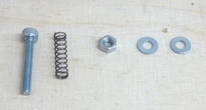
| |
| Item | Quantity |
| M3 Nut | 1 |
| 15x4mm Spring | 1 |
| M3 Washer | 2 |
| M3x25mm Cap screw | 1 |
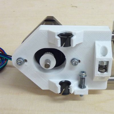
In this step we assemble a Z endstop adjuster. This is used to ensure that the extruder nozzle is just the right height above the bed. Take the M3 cap screw and a washer and insert them into the spring with a washer on the opposite site. This assembly inserts into the small hole on the X motor mount by the bottom clip bearing holder. Place the nut into the slot on the opposite side of the hole and tighten to take up the slack as shwon below (except the X axis will be mounted to the machine at this stage):
Step 4: Z Endstop
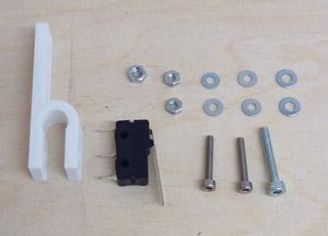
| |
| Item | Quantity |
| Printed endstop holder | 1 |
| Microswitch | 1 |
| M2.5x16mm Cap screws | 2 |
| M2.5 Washers | 4 |
| M2.5 Nuts | 2 |
| M3 x20 Cap screws | 1 |
| M3 Nut | 1 |
| M3 Washer | 2 |
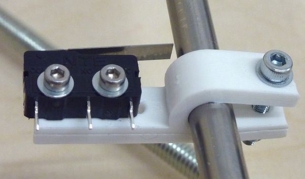
Use the M2.5 washers, nuts and cap screws to clamp the endstop to the endstop holder. You'll notice that the endstop holder has four holes. The endstop should be clamped to the inner most two holes, with the nuts on the large flat side and the lever facing towards bar clamp. Use the remaining M3 fasteners to attach the bar clamp to Z smooth rod on the X motor side. The endstop should be positioned such that it is it is hit by the Z endstop adjuster cap screw.
Step 5: X Belt
Next take the remaining belt from when you part assembled the X axis, and insert the free end into the slot in the right end of the X carriage so that it locks with the teeth of the small length of belt. It should ideally be placed as far into the slot as possible so that the end touches the edge of the narrow gap in the centre of the carriage. Then feed the belt through the X end Idler, around the small bearing, back through the carriage, around the motor pulley and back into the slot on the X carriage as shown below. The tension of the belt is set just like the Y axis.
