Rroofl
This page is a development stub. Please enhance this page by adding information, cad files, nice big images, and well structured data!
Release status: Development
| Description | A Mendel variant designed specifically to be made in a FabLab
|
| License | GPL
|
| Author | |
| Contributors | |
| Based-on | |
| Categories | |
| CAD Models | |
| External Link |
"Don't like society? Print a new one." - Vik Olliver
Contents
Overview
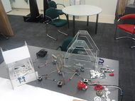
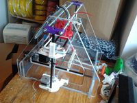
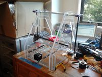
This RepRap/RepStrap variant is designed to be produced in a FabLab, and yet to be sufficiently modular to produce using a variety of local manufacturing processes. It is rather unfriendly to the lone user in its present configuration, as it (a) will make use of all the available CNC-type devices in the workshop in parallel and (b) doesn't work yet. It sprang out of a 2-day session organised by User:VikOlliver and about a dozen hard-working volunteers at FabLab8 in Wellington, New Zealand. They are invited to add their names to the list when they find out about this page :)
Design Objectives
- Completely Open Source
- As many parts as possible to be able to use more than one fabrication technique.
- All routing cuts at least 6mm wide.
- No little extra bits to bolt on - minimize part count.
- If you do use bolts and threaded rod, either M3 (or 1/8") or M8 (or 5/16") please.
- If a zip tie or woodscrew does the job instead of 8 screws, 4 nuts and 16 washers, use one.
- Common parts only.
- Allow for lots of variation in hand-cut parts like the rods.
- Modular design that can be mass-produced, and modules used in other projects.
- Control systems capable of being scaled to drive other workshop equipment.
- Runs off 12-14V DC to be friendly to small, local, power generation systems.
Current Status
Electronics assembled but untested and in need of a rewiring - note that stepper motor STEP & DIR pins must not be longer than about 100mm.X Axis uses the carriage from Simpleton prototype slightly hacked by a nice lady at Fab8nz, a NEMA17 and 3 x 608 bearings as corner pulleys. Tension in belt will draw underconstrained Z sliders onto Z guide rods. The unconstrained sliding portion of the carriage needs to clip more firmly onto the X rail.
Y axis fully assembled, bar the zero switch. Uses 5mm zip ties in the frame to hold both NEMA17 drive motor and the idler. Needs to be measured and the cutting files updated.
Z Assembled, currently using non-spec. gears. Sockets for 608 bearings were not deep enough, the waterjet cut holes in the frame to support Z brackets need to be +0.5mm diameter. The Z motor bracket needs to allow the motor to drop down an extra 3mm to mesh properly with the large driven gear.
The deposition bed is a simple piece of plastic sheet stuck down with double-sided foam, so it needs no fancy holes. Y carriage is in 2 identical parts joined with M8 rod. Y belt secured to carriage with zip ties, which also tension it.
It looks like we can drop all the holes in the lower part of the frame (and the top edge of both short ends) by about 15mm to increase our build height a bit. If we take another 5mm off the top edges we can claim that back for build height by dropping the height of the Y carriage a bit.
The circuit holding panel needs to move up and away from the build area, and needs a hole matrix for mounting Arduinos etc. on.
When cable paths are established, we need mounting holes for cable ties so we can tidy them up.
A stepper motor module capable of driving 2A and made from FabLab inventory is being designed.
Files
Please link or add your files here, folks.
Basic Rules of Enagement
Any rules or warnings that should be established before using the Rroofl can be included here. For example, a safety related tip would definitely make a good addition to this section (thanks for the reminder, OHM).
- Do touch, but touch responsibly.
- During assembly, look out for sharp bits of wire in the edge of the belt. They hurt.
Ongoing Development
There should be some more information here...


