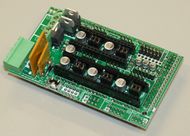
SMART RAMPS
Release status: Working
| Description | RepRap Arduino Due Pololu Shield
Arduino Due based modular RepRap electronics.
|
| License | |
| Author | |
| Contributors | |
| Based-on | |
| Categories | |
| CAD Models | |
| External Link |
Contents
Summary
In SMART RAMPS 1.4.1, the resistors and capacitors are now surface mount to fit more passive components. This does add another set of steps to assembly, but we stuck with larger sizes to make it fairly painless.
- Please clarify: Photo is a photo of a Ramps 1.3 ? Presentation tells the processor is on board, which is not the case ?
- Please clarify: publicised as a 32 bit board, but AT mega (8 bits) mentioned multiple time in the page, while is supposed to be ATSAM3X8E ?
- Please clarify: Presentation indicates SD-card connection is on board, not visible on photo nor schematics
- Please clarify: Presentation indicates possibility to connect thermocouple, no visible direct connection, please indicate if daughter board is needed, references and connection
- Please clarify: What kind of fuses are used ?
- Please clarify: Voltage accepted on inputs. ATSAM is 3.3V only processor, destroyed by 5V, is the board protected in case of 5V input? 5V is mentioned in the servo connection and a lot of times in the page?
- Please clarify: Elaborate specification, acceptable OPERATIONAL voltages and currents for ALL connections, need for cooling, tests ? page seems a cone of Ramps page
Reference board orientation is component side up, power inputs to the left.
Source Files
Schematic Diagram
PCB Board
Safety Tip
Once you start putting electricity into your RepRap - even at just 12 volts - you have to take basic, common sense precautions to avoid fires. Just in case these fail, test your workshop smoke detector. Got no smoke detector? Get one!
Firmware and Pin Assignments
Firmware For SMART RAMPS
Pin definitions
#if MOTHERBOARD == 408
#ifndef __SAM3X8E__
#error Oops!  Make sure you have 'Arduino Due' selected from the 'Tools -> Boards' menu.
#endif

#define KNOWN_BOARD
#define CPU_ARCH ARCH_ARM
/*****************************************************************
* Arduino Due Pin Assignments
******************************************************************/

#define ORIG_X_STEP_PIN     54
#define ORIG_X_DIR_PIN      55
#define ORIG_X_MIN_PIN      3
#define ORIG_X_MAX_PIN      2
#define ORIG_X_ENABLE_PIN   38

#define ORIG_Y_STEP_PIN     60
#define ORIG_Y_DIR_PIN      61
#define ORIG_Y_MIN_PIN      14
#define ORIG_Y_MAX_PIN      15
#define ORIG_Y_ENABLE_PIN   56

#define ORIG_Z_STEP_PIN     46
#define ORIG_Z_DIR_PIN      48
#define ORIG_Z_MIN_PIN      18
#define ORIG_Z_MAX_PIN      19
#define ORIG_Z_ENABLE_PIN   62

// Note that on the Due pin A0 on the board is channel 2 on the ARM chip
#define HEATER_0_PIN   10
#define TEMP_0_PIN     11  // Due analog pin #
#define HEATER_1_PIN   8
#define TEMP_1_PIN     12  // Due analog pin #
#define HEATER_2_PIN   9
#define TEMP_2_PIN     13  // Due analog pin #

#define ORIG_E0_STEP_PIN    26
#define ORIG_E0_DIR_PIN     28
#define ORIG_E0_ENABLE_PIN  24

#define ORIG_E1_STEP_PIN    36
#define ORIG_E1_DIR_PIN     34
#define ORIG_E1_ENABLE_PIN  30

#define SDPOWER   -1
#define SDSS   53 // 10 if using HW SPI. 53 if using SW SPI
#define LED_PIN   13
#define ORIG_FAN_PIN   9
#define PS_ON_PIN      12
#define KILL_PIN   -1
#define SUICIDE_PIN    -1  //PIN that has to be turned on right after start, to keep power flowing.
Final Setup
Pre-Flight Check
If you think you may have mistakes you can install only one stepper driver during initial testing and risk only one stepper driver.
The trimpot on the stepper drivers controls the current limit. Turn it all the way down (counter clock wise) and back up 25%. Be careful to not force the trimpot, it is delicate. You will need to fine tune the current limit later. Note that it is allways giving the motors that much power, even when not moving, so if your stepper motor drivers are getting hot, you may want to turn it down slightly.
Connect the minimum endstops for X,Y, and Z
Connect Motors (Do not disconnect or connect motors while powered; if the connection is loose, this will cause the motors to spazz and possibly kill your stepper driver.)
You may want to use this code to test all the electronics before installing any of the suggested firmwares.
Install firmware (More info below). Firmware flashing can be done without 12V power supply connected.
Wiring
It is relatively simple to wire up the RAMPS. Just add the extruder heating coil wire to D10, the thermistor to the two T0 pins on middle right right, and wire up the steppers and endstops. From left to right, wire all of the stepper motor's wires as red, blue, green, and black or red, green, yellow, blue into the pins next to the Pololus. When you connect the wires to the endstops (if you are using 3 endstops, plug them into the MIN (-) slots), make sure you match the labels.
Note that Tesla & Tonok firmware use D9 and Sprinter, Marlin, and Johnny/Tonok use D10 for the extruder hot end.
Warnings
Reversing +/- or otherwise incorrectly connecting power can destroy your electronics and cause fire hazard.
Incorrectly inserting stepper drivers will destroy your electronics and cause a fire risk. Always make sure power and USB is disconnected when removing or adjusting stepper drivers. Always make sure to insert drivers in correct orientation and in the socket correctly.
The endstop pins are Signal - GND - VCC, instead of the VCC - Sig - GND like the rest of RepRaps boards. Make sure to wire them correctly. This is done to allow squeezing fatter traces on the printable board.
DON'T secure Arduino/RAMPS with conductive screws through both mounting holes. The screw may cut into the positive trace creating a HIGH current short.
Connecting Power
Connect your 12V power supply to the RAMPS shield. Reversing +/- or otherwise incorrectly connecting power can destroy your electronics and cause fire hazard.
The bottom pair of connectors marked 5A power the stepper drivers and Extruder heater/fan (D9, D10). The source should be rated a minimum of 5A.
The pair of connectors above marked 11A power a Heated Bed, or other output (D8). The source should be rated a minimum 11A (if both power rails are connected to the same supply it should have a minimum rating of 16A).
The barrel connector, on the Arduino MEGA, will NOT power RAMPS and will not provide power to the stepper motors, heated bed, etc.
The power connector plug may not be obviously labeled, looking at the power connection the positive is on the left and the negative is on the right of the plug.
Power Supply
RAMPS is quite happy with the 12 V line from PCPowerSupply. Or you can hack up a 12V laptop power supply, or other 12 V "wall wart" power supply. Make sure that the power supply can output 5A or greater. Additional 11A may be needed for heated bed support.
See Connecting power above.
The 3 pins next to the reset switch are meant to optionally connect to your PSU.
The PS_ON pin is intended to switch your power supply on and off. Many firmwares support pulling this pin low with M80 command to turn the power supply on, and M81 to turn it off. This behavior is desired for ATX power supplies and can be modified in firmware to support 5V high power supplies like those borrowed from an Xbox.
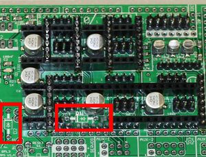
Without D1 installed, or when the 12VIN is not connected, the Arduino gets its power from USB. If you want your kit powered without USB connected you need to solder in D1 OR connect VCC to your PSU.
The VCC pin can be connected to your ATX's 5Vsb to continuously power the Arduino from your ATX power supply. You will want to make sure that D1 is not installed or cut out. The Arduino is not designed to be powered directly on the VCC rail and the VIN pin at the same time.
If you want to use PS_ON to turn on your power supply then don't use diode D1, you need your Arduino to be powered from 5Vsb otherwise when no USB is connected the PS_ON pin floats (and your power supply pulses on and off).
The 5V pin in that connector on RAMPS only supplies the 5V to the auxiliary servo connectors. It is designed so that you can jumper it to the VCC pin and use the Arduino's power supply to supply 5V for extra servos if you are only powered from USB or 5V. Since there is not a lot of extra power from the Arduino's power supply you can connect it directly to your 5V power supply if you have one. You can also leave this pin not connected if you have no plan to add extra servos.
Maximum Input Voltage
Power Supply without diode
There are three limiting factors to the maximum voltage that you can put into the RAMPS:
- The Arduino Mega maximum input voltage
- Filtering capacitor maximum voltages
- PTC fuse maximum voltages
First, the 1N4004 diode connects the RAMPS input voltage to the Arduino Mega which has a recommended maximum input voltage of 12 volts. If your board does not have this diode soldered in (or if you cut it), you will need to power the Mega through the USB connector or through a separate 5v line, but this allows a higher RAMPS voltage.
Second, most boards use 25v or 35v aluminum electrolytic capactors (C2, C3, C4, C6, C7, C9, and C10). To be safe, you should only go to half of your rated maximum voltage -- thus if your board has 35v capacitors (code VZA) then you should use a maximum input of 17.5v. The absolute maximum voltage is determined by the pololu servo drivers, which themselves are limited to 35V.
Third, the MF-R500 (5A) PTC fuse is rated to 30V and the MF-R1100 (11A) PTC fuse is rated to 16V. They will need to be replaced with real fuses.
Power Supply with diode
If your board has a 1N4004 diode soldered in, do not apply more than 12 V to it. Original flavor Arduino Mega are rated to 12 V input. While Arduino Mega 2560 can take 20 V, it is not recommended.


