Sanguinololu
Release status: experimental
| Description | Complete electronics control for Reprap
|
| License | unknown
|
| Author | |
| Contributors | |
| Based-on | [[]]
|
| Categories | |
| CAD Models | Eagle
|
| External Link |
Contents
Introduction
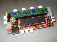
Here is a project I've been working on. It started in this forum thread. I would like a nice clean board to control my currently un-born Reprap, and due to its cost and simplicity I've chosen to use the Sanguino Arduino compatible board paired with a set of Pololu Allegro A4983 Stepper Motor Driver Carrier boards. In order to keep things tidy, I've mushed all this into one board.
Latest Updates
Latest revision: 0.7 Updated March 3, 2011
The revision 0.6 PCBs have been shipped! Now for their trek across the Pacific.... In order to keep prices cheap, there will be a surplus of these boards. drop me a line in irc if you want a sample. And to source the parts I've created a parts list on [www.mouser.com].
Please note that the 0.6 revision does not have pads for the voltage regulator (added in 0.7), and in order to be powered by USB bus, a greenwire must be soldered.
The first prototype, revision 0.1, is completely working, though required a minor fix in the form of a green-wire to enable power-by-usb
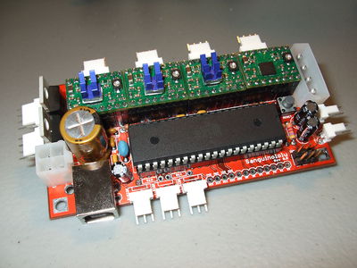
Features
- Small design - board is 100mm x 50mm (4" x 2"), 2 sided, a bunch of vias (DIY routed 1 sided design in the works)
- Sanguino clone, Atmel's ATMEGA644
- Up to 4 Pololu (or Pololu compatible) on-board (X,Y,Z,Extruder) (A4983 without voltage regulator)
- Supports multiple power configurations
- Logic & Motors supplied by ATX power supply (needs molex harddrive connector, and optional 4pin atx connector for additional 12v)
- Motors supplied by 5mm screw terminal (7v-35v)
- Logic supplied by USB bus (if connector is installed)
- Logic supplied by optional on-board voltage regulator (molex harddrive connector cannot be installed at the same time)
- Supports multiple communication configurations
- FT232RL on-board for USB connectivity
- USB2TTL header is available for FTDI cable, or BlueSMIRF bluetooth module
- Edge connectors for all wire connections, for vertical jumpers or right-angle tidyness, with or without polarizing tab
- Silkscreen for connectors on both sides of the board, facilitating bottom cable connections for even more tidyness
- Sanguino extra pin header for expansion (6 analog IO and 4 digital IO - two for uart2, and two PWM pins)
- All through-hole components (except FTDI chip) for easy DIY soldering
- 2 thermistor connectors with circuitry
- 2 N-MOSFETs for extruder/bed, or whatever
- Selectable 12v/5v endstop voltage
Schematic & Board Images
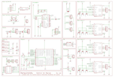
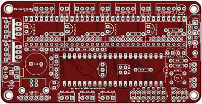
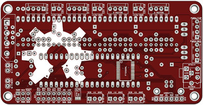
These images are from the working 0.7 branch and may not reflect the latest EAGLE files.
EAGLE files
https://github.com/mosfet/Sanguinololu
Revision History
Rev 0.7 Added footprints for voltage regulator for those wanting to use laptop power brick, etc. The vreg component footprints are hidden under the ATX power supply for space saving and to prevent both from being in use.
Enabled USB bus power for logic side.
Connected the 5v pin on the USB2TTL header so that either a: ftdi cable can power the board, or b: The board can power a bluetooth serial module (bluesmirf).
Rev 0.6
Made changes suggested regarding putting power pin in the middle of endstop sense connector.
Shrunk board to metric specifications for boardhouse - board size now 100mm x 50mm - just a tad smaller than 4"x2"
Increased spacing between connectors to facilitate polarized or locking connector types / wire headers
Changed orientation of MS1/2/3 jumpers to (hopefully) make it easier to remove / put on, and give more room to the pololu decoup caps
Sent design to boardhouse for prototypes
Rev 0.3
MS1/2/3 for each motor separated. Unfortunately the best place for this to go is under the pololus, needing you to remove the pololu to change it's microstepping settings. Oh well, I'm hoping this is a set-it-and-forget-it type of thing.
Added optional 4-pin atx 12v connector to support large hotbed or extruder loads, up to 20A. 3A if just using the hdd connector
Adjusted schematic to put MOSFETs gates on PWM pins for less software intense temp control.
Moved endstop connectors to other side of board.
Added 12V power connectors in their place, for always on fan, or whatever. Watch out for current rating. Maybe a couple of fuses is in order....
Rev 0.1
First prototype, first design, first PCB ordered, first assembled, etc. Pics: [imgur.com]
