Sanguinololu
Release status: working

| Description | Release Version 1.2
|
| License | unknown
|
| Author | |
| Contributors | |
| Based-on | |
| Categories | |
| CAD Models | Eagle
|
| External Link |
Contents
Introduction
<videoflash type="vimeo">23472226|384|288</videoflash>
Sanguinololu is a low-cost all-in-one electronics solution for Reprap and other CNC devices. It features an onboard Sanguino clone using the ATMEGA644P though a ATMEGA1284 is easily dropped in. Its four axes are powered by Pololu pin compatible stepper drivers.
The board features a developer friendly expansion port supporting I2C, SPI, UART, as well as a few ADC pins. All 14 expansion pins can be used as GPIO as well.
The board is designed to be flexible in the user's power source availability, allowing for an ATX power supply to power the board, or the user can chose to install the voltage regulator kit for use with any power supply 7V-30V.
Latest Updates
Latest revision: 1.2 Updated June 15, 2011
While Version 1.1 is completely functional, there were some requests from users for pin assignment changes. Version 1.2 implements these changes. --Z-Enable is now on its own pin --PWM devices have been moved to OC0 and OC1 freeing up OC2 for internal timing --The expansion port is now a pin shorter - the Z-Enable feature ate an analog pin here.
Version 1.2 still includes the footprint for the Molex HDD connector, though you may be wise to disregard it and always install the 5V regulator as not all ATX power supplies' 5v lines are stable and clean.
Latest posts in the Forum
Features
- Small design - board is 100mm x 50mm (4" x 2") - barely an inch longer than a business card!
- Sanguino clone, Atmel's ATmega644P - ATmega1284 drop-in compatible!!
- Up to 4 Pololu (or Pololu compatible) on-board (X,Y,Z,Extruder) (A4983 without voltage regulator)
- Supports multiple power configurations
- -- Logic & Motors supplied by ATX power supply (needs molex harddrive connector, and optional 4pin atx connector for additional 12v/supply voltage)
- -- Motors supplied by 5mm screw terminal 7-35V
- -- Logic supplied by USB bus
- -- Logic supplied by optional on-board voltage regulator (molex harddrive connector cannot be installed at the same time)
- Supports multiple communication configurations
- -- FT232RL on-board for USB connectivity
- -- USB2TTL header is available for FTDI cable, or BlueSMIRF bluetooth module
- 2 thermistor connectors with circuitry
- 2 N-MOSFETs for extruder/bed, or whatever
- Selectable 12v(or supply voltage)/5v endstop voltage
- Edge connectors enabling right-angle connections
- Silkscreen for connectors on both sides of the board, facilitating bottom cable connections
- 14 Extra pins available for expansion and development - 6 analog and 8 digital, with the following capabilities
- -- UART1 (RX and TX)
- -- I2C (SDA and SCL)
- -- SPI (MOSI, MISO, SCK)
- -- PWM pin (1)
- -- Analog I/O (6)
- All through-hole components (except FTDI chip) for easy DIY soldering
Schematic & Board Images
Renders
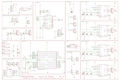
Schematics
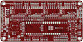
Top board
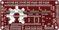
Bottom board


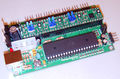
Photos
Assembled rev 0.1 board
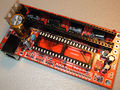
Mostly Assembled rev 0.5 board
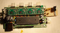
Assembled rev 0.6 board with Ad-hoc VREG on Stripboard


Where to get it?!
You can get the bare pcb or a complete kit at eMAKERshop
(if any other resellers have this available, please add to this section)
You will also need Pololu or Pololu compatible stepper drivers such as StepStick
EAGLE files, parts list
Schematics, board, images: https://github.com/mosfet/Sanguinololu/tree/master/rev1.1
Parts: https://github.com/mosfet/Sanguinololu/tree/master/rev1.1/parts.txt
Mouser part projects
Everything you need except the PCB!
| Project Name | Project Description | Price (as of 4-7-2011) |
|---|---|---|
| Sanguino Core (all versions) | The base project. Does not include FTDI implementation or power connectors. Chose this and then chose add-ons from below. | $21.95 (USD) |
| ATX power connector kit | Vertical plugs for using the ATX power supply's ATX+4 12V connector and 4 pin HDD connector. If you install this, you can't install the Screw terminal & Voltage regulator kit... but why would you want to anyway. | $1.86 (USD) |
| Screw terminal & Voltage regulator kit | 5mm Screw terminal and voltage regulator (and supporting parts) for those not wanting to use an ATX power supply, or would rather use a single volt power supply, 7-24V (25v if you install larger caps). If you've been following along, you know that if you install this, you can't install the ATX power connector kit. | $1.55 (USD) |
| FTDI & USB plug kit | This kit includes a USB type B connector and a SSOP FTDI FT232RL chip (and supporting parts) commonly used for serial communication over USB. | $5.30 (USD) |
| Polarized Connector Kit | Polarized right-angle connectors for the edge, and matching cable housings. Cable side is easy pinch type connectors, so no soldering or crimping is needed. | $4.30 (USD) |
If you expect your heated bed to use a lot of current (say more than 5A) you may care to use an IRF2804PbF MOSFET in place of the RFP30N06LE one specified for Q2. The RFP30N06LE has an on resistance of 47 mohms, but the IRF2804PbF has an on resistance of only 2 mohms.
Assembly Instructions (Version 0.7 - 1.2)
For older versions see Sanguinololu_0.6
Introduction
Gather the tools you will need to perform push through hole soldering, and if you opted for the on-board FTDI kit, some SMT soldering as well. Soldering pencil and/or iron, solder, and most importantly: flux! I can't stress how much easier flux makes soldering the SMT device.
Carefully inspect your board for defects. Look for strange connections between traces. Become familiar with the locations of devices from the back as well as the front.
Gather your components and ensure you have the complete parts list for your selection. This photo shows enough parts for two Sanguinololus - one with ATX connectors and the other with screw terminal and voltage regulator.

Soldering the FTDI
Install the FT232RL FTDI IC. Note the orientation of the silkscreen. Solder using your favorite SMT soldering method. The board pictured was tinned from the fabrication shop. After applying flux to the pads, and carefully placing the chip, it was easily soldered by touching the tip of the soldering pencil to the end of pad to tack the chip down, and then on the pin it self to flow the solder correctly. If you're not sure you want to tackle the SMT soldering, you can get the PCB with the USB pre-soldered [here].
Parts:
IC100 FT232RL FT232RLSSOP
<videoflash type="youtube">bvo8Xj_yn3w|640|360</videoflash>


Next install the FTDI components. mind the polarization on the electrolytic (C16).
Parts:
 J1       USB              USBPTH
 C7       0.1uF            CAPPTH2
 C8       0.1uF            CAPPTH2
 C11      0.1uF            CAPPTH2
 C15      0.1uF            CAPPTH2
 C16      4.7uF            CAP_POLPTH2

Now is a good time to test the FTDI chip. Plug a USB cable into the port. The device should show up as a COM port or a TTY device and allow it to be opened. If you temporarily connect the 'TX' and 'RX' pins on the USB2TTL port on the back of the board anything you type in your terminal application (such as PuTTy) should be echoed back to you.
Soldering Sanguinololu Core
Next, solder the female headers, making sure they're straight and completely seated on the PCB. Where two lengths of header strip are placed so they join in the middle, they may be fractionally too long to lie flat on the board at the join. In this case, carefully file off some of the plastic at the adjoining ends until they fit together in the space available.
Parts:
4x Female Pin Header 16 Pin

Solder ms1 jumper headers. I find that it is easier to solder the 2 pin header if the jumper shunt is installed. Ensure they're completely seated and straight.
Parts:
 12x Male Pin Header 2 Pin
 12x Jumper Shunt

Install the led current limiting resisitor and the MS1 pulldown resistors.
Parts:
 R1       1.5k             RESISTORPTH1
 R2       100k             RESISTORPTH1
 R3       100k             RESISTORPTH1
 R4       100k             RESISTORPTH1
 R5       100k             RESISTORPTH1

Solder the driver decoupling caps. Before soldering, bend the leads to the side so the capacitor lays down. Mind the polarization!
Parts:
 C1       100uf            CAP_POLPTH1
 C2       100uf            CAP_POLPTH1
 C3       100uf            CAP_POLPTH1
 C4       100uf            CAP_POLPTH1

Install the thermistor high pass RC filters. Mind the polarization of the capacitors. Install the MOSFET pulldown resistors as well as the UART current limiting resistors.
- Update!*
The current limiting resistors for the UART are not needed and in some cases can limit communication speeds. It is recommended to instead install just a wire in place of R7 and R8. TODO: Insert pic of r7 & r8 zero ohm
Parts:
 R6       10k              RESISTORPTH1
 R11      10k              RESISTORPTH1
 R7       1k               RESISTORPTH1
 R8       1k               RESISTORPTH1
 C9       10uF             CAP_POLPTH2
 C10      10uF             CAP_POLPTH2
 R9       4.7k             RESISTORPTH1
 R10      4.7k             RESISTORPTH1

Install the dip socket and ceramic resonator. Before soldering, bend the resonator leads so that it lays down within the dip socket. It doesn't matter which way round it goes.
Parts:
 DIP-40   SOCKET
 Y1       16MHz 22pF       RESONATORPTH

Install the two ceramic caps for the ATMEGA and the reset pull up resistor.
Parts:
 C14      0.1uF            CAPPTH2
 C13      0.1uF            CAPPTH2
 R12      100k             RESISTORPTH1

Solder the MOSFET, the large charge capacitor, reset button, and the power led. The power led's negative lead is the flat side, or shorter lead. The negative lead goes to the left in the picture immediately below.
Parts:
 Q1       RFP30N06LE       MOSFET-NCHANNELPTH2
 Q2       RFP30N06LE       MOSFET-NCHANNELPTH2
 C12      1000uF           CAP_POLPTH4
 S1       RESET            TAC_SWITCHPTH
 LED1     POWER            LED3MM

ATX Power Supply Source
If you are using the ATX power supply kit, install those connectors.
Parts:
 ATX1     ATX-4VERTICAL    ATX-4VERTICAL
 HDDPWR   5v/12v           DRIVEPWRVERTICAL

Important Note:
It has been brought to my attention in IRC (thanks Kliment & tonokip) that the 5V coming from the ATX power supply may not be as stable and at 5V as one could hope. It would be better practice here to instead of using the 4-Pin hard-drive connector use the 4-pin ATX connector and the Voltage Regulator. The 4xATX connector will still provide enough power for the board.
One could even forgo the voltage regulator and power the logic side of the board strictly by USB, the power side by 12V ATX4.
Voltage Regulator & Screw Terminal
If you are using the voltage regulator and screw terminal kit, install those parts now. Note the orientation of the LM7805. Label the screw terminal with a felt tip marker which side is + and which is -. Note - on later versions of this board the screw terminals mount at right angles to the way shown so the wire they connect comes out parallel to the USB lead.
Parts:
 IC1       LM7805          VREG
 C5       0.33uF           CAPPTH2
 C6       0.1uF            CAPPTH2
 JP23     SCREW            M025MM

Connectors
Finally, solder your motor, end stop, thermistor, and bed/tip connectors. Optionally solder the 12v(or supply voltage) connectors on the top of the board, and the ISP 6 pin header (for programming the ATMEGA) Various parts.

For speeding up the soldering of the connectors in case you use pinheaders, you can use longer strips, and just snip positions that are not used, like this:


(Top strip left, endstops right)
Resulting in a board like this

Pololus
When you solder the pin strips onto the Pololus you will find it easiest to put the strips in the appropriate place in the Sanguinololu. Then just drop the Pololu boards on top and solder them in place. You can then unplug them later if you want.
Endstops
Mechanical micro-switch endstops are recommended for their simplicity and reliability. It is recommended to wire the switch terminals Common (C) and Normally Open (NO) to GND and SIG on Sanguinololu (the two outside pins on the endstop connectors). Ensure you set Endstops_Inverting to true in your firmware.
If you are using optical endstops or proximity sensors (or other endstops that require power) you can use either 5v or 12v(or supply voltage) depending on what endstop device you want to use. This is selected by soldering a little link labeled "Stop Volt" on the back of the board. With the text the right way up, joining the left pad to the middle one gives 12v(or supply voltage); right-to-middle gives 5v. Take care not to short all three together.
Powering Sanguinololu
Your chosen power solution will determine what kind of power requirements will be in play:
Voltage Regulator & Screw terminal kit: Connect your power supply with at least 7V and at most 30V to the screw terminal. The negative lead is the one closest to the screw hole.
ATX Power Connectors: Connect a Molex HDD cable to the connector on the right side of the board. This cable provides enough power to supply the motors as well as the on board logic chips, and a extruder heater. If you plan on powering your hotbed with Sanguinololu, or if your power supply doesn't supply enough power over the Molex plug you should also connect the ATX-4 pin connector. The ATX power supply must also be rigged to turn on when plugged in & the switch is on. This is done by shorting the !PWR_ENABLE pin to ground on the main ATX-20 pin connector. This is usually the green wire shorted to a black wire. I use a staple crammed in the socket, and use the switch on the power supply case to control system power.
Sanguinololu Firmware
You can program the ATMEGA644P with Sanguino's [bootloader] for easy firmware loading.
Sprinter is the recommended firmware for Sanguinololu.
Check the Configuration.h to ensure that Sanguinololu is selected as your board (board 6). Also check pins.h to ensure the pin layout matches your version of board - if you have a version 1.2 board (printed near the corner screw hole) make sure you uncomment the Sanguinololu_V_1_2 declaration in pins.h
Pin Assignments v1.2
                           +---vv---+
    e-dir      (D 0) PB0  1|        |40  PA0 (AI 0 / D31) ext
   e-step      (D 1) PB1  2|        |39  PA1 (AI 1 / D30) ext
    z-dir INT2 (D 2) PB2  3|        |38  PA2 (AI 2 / D29) ext
   z-step  PWM (D 3) PB3  4|        |37  PA3 (AI 3 / D28) ext
      ext  PWM (D 4) PB4  5|        |36  PA4 (AI 4 / D27) ext
      spi MOSI (D 5) PB5  6|        |35  PA5 (AI 5 / D26) !sstep-enable-z
      spi MISO (D 6) PB6  7|        |34  PA6 (AI 6 / D25) b-therm
      spi  SCK (D 7) PB7  8|        |33  PA7 (AI 7 / D24) e-therm
                     RST  9|        |32  AREF
                     VCC 10|        |31  GND
                     GND 11|        |30  AVCC
                   XTAL2 12|        |29  PC7 (D 23)       y-dir
                   XTAL1 13|        |28  PC6 (D 22)       y-setp
    ftdi  RX0 (D 8)  PD0 14|        |27  PC5 (D 21) TDI   x-dir
    ftdi  TX0 (D 9)  PD1 15|        |26  PC4 (D 20) TDO   z-stop
     ext  RX1 (D 10) PD2 16|        |25  PC3 (D 19) TMS   y-stop
     ext  TX1 (D 11) PD3 17|        |24  PC2 (D 18) TCK   x-stop
 !hotbed  PWM (D 12) PD4 18|        |23  PC1 (D 17) SDA   ext
 !hotend  PWM (D 13) PD5 19|        |22  PC0 (D 16) SCL   ext
!step-en  PWM (D 14) PD6 20|        |21  PD7 (D 15) PWM   x-step
                           +--------+
Or in tabular format
 !stepper-enable D14        PB4
 e-dir           D0        PB0
 e-step          D1        PB1
 z-dir           D2        PB2
 z-step          D3        PB3
 y-dir           D23       PC7
 y-step          D22       PC6
 x-dir           D21       PC5
 x-step          D15       PD7
 !hotbed         D12       PD4
 !hotend         D13       PD5
 b-therm         D25  AI6  PA6
 e-therm         D24  AI7  PA7
 x-stop          D18       PC2
 y-stop          D19       PC3
 z-stop          D20       PC4
Pin Assignments v0.7 - 1.1
 stepper-enable D4        PB4
 e-dir          D0        PB0
 e-step         D1        PB1
 z-dir          D2        PB2
 z-step         D3        PB3
 y-dir          D23       PC7
 y-step         D22       PC6
 x-dir          D21       PC5
 x-step         D15       PD7
 hotend         D13       PD5
 hotbed         D14       PD6
 b-therm        D25  AI6  PA6
 e-therm        D24  AI7  PA7
 x-stop         D18       PC2
 y-stop         D19       PC3
 z-stop         D20       PC4
Revision 0.5 / 0.6 Info
See Sanguinololu_0.6 for assembly instructions, board files, etc.
Revision History
Rev 1.1 Corrected silkscreen mistake. Added open hardware logo
Rev 1.0 Release revision, tighter DRC rules, and updated screw terminal footprint. Looks like there is one tiny mistake on the 1.0 board: the leftmost 5v pin on the expansion header is actually 12v(or supply voltage).
Revision 1.0 is here with only a few tiny changes from 0.7 - the screw terminal pads have been rotated so that they face the closest edge, and the design rules have become more strict to be compliant with more board fab shops. I've included gerber files in git so that you can easily have your own boards fabbed.
Rev 0.7 Added more pins to the expansion header, made I2C and SPI available for use. Combined all stepper motor enable nets into one pin.
Added footprints for voltage regulator for those wanting to use laptop power brick, etc. The vreg component footprints are hidden under the ATX power supply for space saving and to prevent both from being in use.
Enabled USB bus power for logic side.
Connected the 5v pin on the USB2TTL header so that either a: ftdi cable can power the board, or b: The board can power a bluetooth serial module (bluesmirf).
See Sanguinololu_0.6 for older revision history