Sarrus Z Linkage
Release status: unknown

| Description | Sarrus Z axis model Z01
|
| License | unknown
|
| Author | |
| Contributors | |
| Based-on | |
| Categories | |
| CAD Models | |
| External Link |
I am exploring the Sarrus linkage. I think that it has the potential to make mostly printable linear bearings.
This is an attempt at making a Z axis that would be suitable for lifting a platform on which to print, or maybe holding an extruder from above.
It is a continuation of a series of attempts to use simple hinges to make complicated things.
So far the RepRap has printed
- Sarrus Z01
- Sarrus Z02
- Sarrus L04
- Sarrus Linkage Mark III by fdavies, used to build a "2-axis printable shaftless linear actuator"[1]
- ...
- ... any other Sarrus-type linkage? ...
Frank Davies posts a lot of work on thingiverse, much of it related to 3D printed Sarrus linkages.
Sarrus Z01 linkage
I have named it the rather uninspired name of Z01 because it is just one part of a much bigger story, I hope. When I have a Sarrus based printer, I will probably name it Sarrus, to honor mathematician who came up with the fundamental geometry and to continue the reprap tradition of naming machines after people from the 19th century.
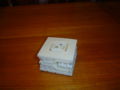
Model Z01 in closed state
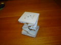
Model Z01 in halfway state
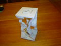
Model Z01 in fully open state


Contents
Instructions
Print one each of the end plates. Print 4 of plate_a and 4 of plate_b. These have an overhang, but using the 'support on exterior only' setting on Skeinforge gives workable results. Also, teh plate_ab_merged file allows you to print the hinge plates in pairs.
Drill out all the small holes with a 1/16" drill bit, then use 1/16" brass rod to make hinge pins.
Features
- Intended to be printable on a Makerbot Cupcake (but I have not done it).
- Total range of motion 102 mm.
- Hole for mounting skate bearing (608).
- Room for 10-32 or similar threaded rod
- Mounting hole for 10-32 nut.
- Flexure for allowing sideways shifts of 10-32 nut.
Performance evaluation
The Z01 is not stiff to rotation of the end pieces. If you hold one end and push sideways (at a right angle to the axis of motion), that end moves and rotates. This is because the hinge plates twist slightly. It is not due to hinge looseness. Inperfections in the drive rod (10-32) like bends and bearing imperfections push it in just that way. I do not think that this is stiff enough for a 3D printer Z axis.
I designed this with Art Of Illusion 2.7.
CAD Files
future research
- Would adding more "link chains" (is there a better word?) of plate_a and plate_b make it sufficiently stiff to rotation?
- instead of 4 chains at 0, 1/4 turn, 1/2 turn, and 3/4 turn, perhaps 8 chains at 0, 1/8, 1/4, 3/8, 1/2, 5/8, 3/4, and 7/8 turn? Or perhaps 6 chains vaguely similar to a Delta ?
- instead of 4 chains in a single square, perhaps 8 chains in two identical squares connected side-by-side? (Does "both identical counter-clockwise" vs "mirror-image CCW and CW" vs make any difference?)
- Would changing the "link chain" design to get more torsional stiffness make it sufficiently stiff to rotation? If you keep the length and cross-sectional area the same (i.e., keep the volume the same), but make them shorter and thicker (moving from a rectangular cross section towards a square cross section), the torsional constant goes up by the square of the thickness.
- Is it possible to replace the brass rod hinges with "living hinge"? If so, then perhaps the entire structure (the two end plates and all the stuff between them) can be printed as a single object, with no assembly necessary.
- Wikipedia: living hinge
- Forrest built a Sarrus linkage prototype.[2]
- Would maybe some other straight-line mechanism or near-straight-line mechanism, such as the ones listed at Wikipedia: straight line mechanism?