ScannerStrap
This page is a development stub. Please enhance this page by adding information, cad files, nice big images, and well structured data!
//work in progress.
Release status: experimental
| Description | Documenting a 3D printer made from a used large format flatbed scanner
|
| License | |
| Author | |
| Contributors | |
| Based-on | |
| Categories | |
| CAD Models | |
| External Link |
Contents
Discussion
Building a 3D printer from used $60 US flatbed scanner.
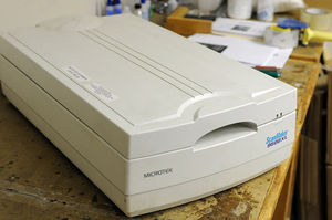
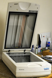
MICROTEK ScanMake 9600XL, large format flatbed scanner. Used, purchased at REPC for $60 in Seattle. This will be used for the bases of the 3D Printer I am building. Primary advantage, this scanner has two scanner slide assemblies, bed and lid, complete with stepper motors, belt drive, dual slide rails. Thus, mounted in the appropriately fabricated superstructure, these components can form the primary basis for the x and y axis for the printer.
X and Y Axis
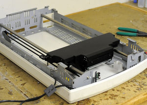
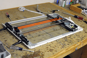
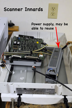
Disassembled top and bottom of scanner and tore out the guts to get at the slide mechanisms.
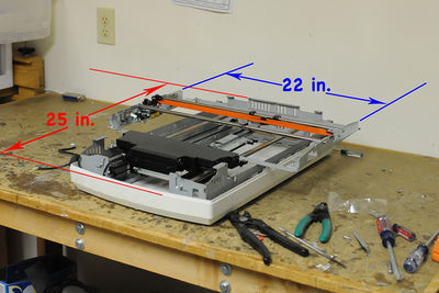
Maximum length and width of printer set by travel of bottom and lid of original scanner. This will determine the size of the wooden superstructure for the printer.
Scanner Stepper Motors
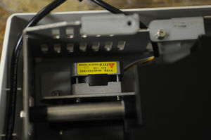
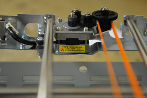
The stepper motor from the bottom of the scanner. Y-axis, is a TECO, TYPE 4H4018X1603, 5V, 1A, Holding Torque-1.2Kg-cm (Bi-POLAR) X-axis, is a TECO, TYPE 4H4018X0101, 12V, 0.23A, Holding Torque-0.8Kg-cm (Uni-POLAR)
Wood Superstructure
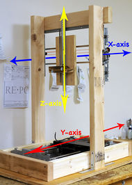
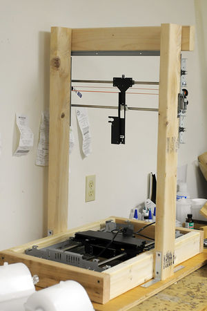
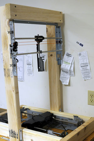
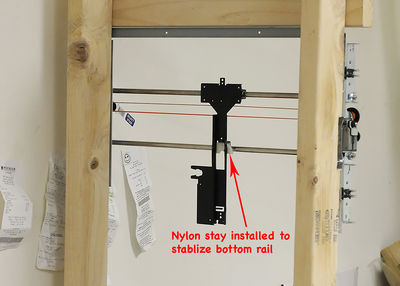
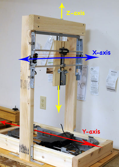
Wood superstructure constructed of 2X4s with a bottom of 3/4" plywood. X-axis from the scanner is mounted in the vertical stand. The Y-axis sets in the bottom of the structure. Both bottom and lid slide systems have only one bushing connected to the rail. This is fine for the the Y-axis because gravity is your friend here. For the X-axis mounted in the vertical a nylon stay was glued to the unattached rail to secure it.
Completed Structure Before Z-axis installed
Approximate build area, Y-axis - 17 inches (432 mm), X-axis - 11 inches (280 mm), Z-axis - 10 inches (254 mm)
Z-axis
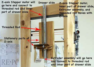
Z-axis will have to be fabricated independent of original scanner. First, a piece of 3/4" plywood was fabricated to mount the X-axis rail system. Z-axis will slide along a center mounted drawer slide (Rockler Center drawer slide, $8.49) . Z-axis stepper motor will be mounted to the top of the drawer slide and the extruder assembly will be mounted to the bottom. Both will be attached to opposite ends of a 3/8 threaded rod. Rotation of the Z-axis stepper motor will move it, the center rail of the drawer slide, and the extruder assembly up and down.
Work Platform
Mounted directly to aluminum carriage assembly with 3/8" x 3" fully threaded bolts. CARB compliant 1/2" birch plywood (soy-based instead of urea-formaldhyde glue) is used for lower and upper work platform. With the upper work platform to have a heated bed I did not want any toxic fumes emitted at these higher temperatures.
