File list
This special page shows all uploaded files.
| Date | Name | Thumbnail | Size | Description | Versions |
|---|---|---|---|---|---|
| 20:04, 21 September 2012 | Rroofl mendel adap.scad (file) | 632 bytes | Simple adaptor blocks to attach the Rroofl Z axis to a Mendel or Prusa style frame with. | 1 | |
| 03:25, 15 March 2007 | StepperMotor-bipolar stepper sch.png (file) |  |
1 KB | Schematic of bipolar stepper motor | 1 |
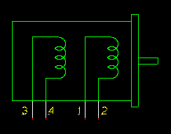
| 03:26, 15 March 2007 | StepperMotor-unipolar stepper sch.png (file) |  |
2 KB | Schematic of unipolar stepper motor | 1 |
| 17:09, 21 September 2012 | Y bed runners.scad (file) | 3 KB | 3 | ||
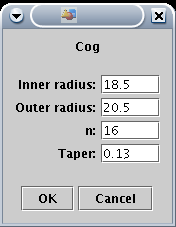
| 01:49, 17 November 2005 | GearDesignInAoI-aoi cog window.png (file) |  |
5 KB | The AoI Cog creation dialogue | 1 |
| 05:09, 17 August 2008 | DarwinPartDevelopment-Z-belt-tensioner-idler.aoi (file) | 7 KB | Idler wheel for Z belt tensioner | 1 | |
| 03:55, 7 May 2006 | MeasuringThermistorBeta-ThermistorBeta.ods (file) | 7 KB | OpenDocument Spreadsheet for calculating thermistor Beta and Rz | 1 | |
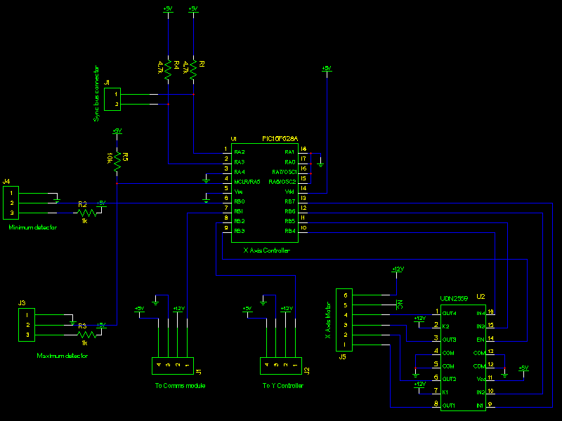
| 06:05, 13 March 2006 | StepperDriverWithUDN2559-xaxis-2559.png (file) |  |
9 KB | Schematic of 2559-based stepper driver. | 1 |
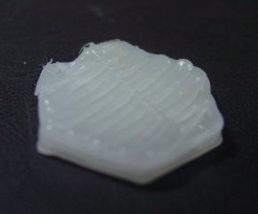
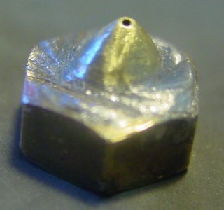
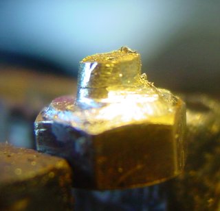
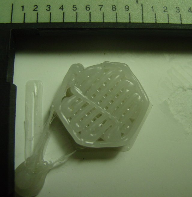
| 10:25, 10 June 2006 | BlogPhotosFromVik-small shot of hexagon.jpg (file) |  |
10 KB | Small shot of hexagon deposited in mov02395.mpg | 1 |
| 01:56, 8 May 2006 | BuildingAStripboardStepperController-xaxis 2803.png (file) |  |
11 KB | Schematic for axis controller using ULN2803 octal driver | 1 |
| 10:35, 16 July 2006 | InterchangeableNozzleMk2-bud shaped dremel bit.jpg (file) |  |
12 KB | Dremel bit used to shape interior of nozzle | 1 |
| 05:10, 17 August 2008 | DarwinPartDevelopment-Z-belt-tensioner-idler.stl (file) | 13 KB | Idler wheel for Z belt tensioner | 1 | |
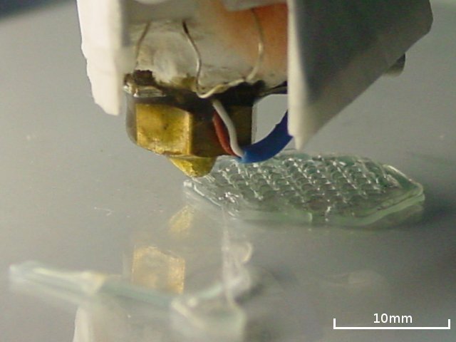
| 09:42, 10 June 2006 | BlogPhotosFromVik-deposition on glass.jpg (file) |  |
15 KB | Still from mov02395.mpg | 1 |
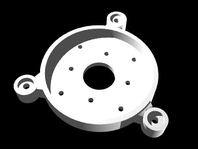
| 03:41, 26 November 2005 | VerticalPlatform-spider rendering.jpg (file) |  |
18 KB | AoI Rendering of the spider designed to hold the gears | 1 |
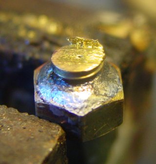
| 10:34, 16 July 2006 | InterchangeableNozzleMk2-final nozzle sanded.jpg (file) |  |
19 KB | 0.5mm Nozzle after shaping and sanding | 1 |
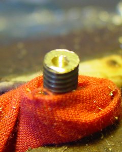
| 10:31, 16 July 2006 | InterchangeableNozzleMk2-nozzle after thread removal.jpg (file) |  |
20 KB | Nozzle in progress. Excess thread removed. | 1 |
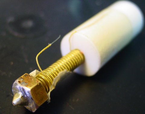
| 05:18, 8 January 2006 | InterchangeableNozzleMk2-detatchable nozzle assy sml.jpg (file) |  |
22 KB | The detatchable nozzle concept. This one has been reduced in diameter with solder around a piece of nichrome wire, which is then removed to leave the vital hole. | 1 |
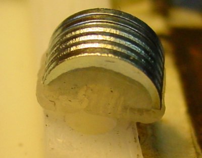
| 10:29, 16 July 2006 | InterchangeableNozzleMk2-cut bolt innut unsoldered.jpg (file) |  |
23 KB | Drilled and cut bolt in M6 nut showing exit hole | 1 |
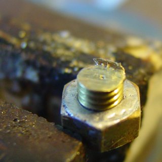
| 09:37, 16 July 2006 | InterchangeableNozzleMk2-M6 bolt with 3mm hole.jpg (file) |  |
23 KB | 3mm hole drilled in M6 bolt. | 1 |
| 01:44, 5 January 2006 | Half-roundWasherBearing-stack of half-washers.jpg (file) |  |
24 KB | Completed stack of half-washers | 1 |
| 10:36, 16 July 2006 | InterchangeableNozzleMk2-nozzle on half finished extruder.jpg (file) |  |
24 KB | Nozzle fitted to a half-finished extruder barrel. | 1 |
| 06:29, 17 November 2005 | GearDesignInAoI-set cog smoothness.png (file) |  |
25 KB | Setting the smoothness of the cog teeth | 1 |
| 10:30, 16 July 2006 | InterchangeableNozzleMk2-cut bolt in nut soldered.jpg (file) |  |
26 KB | Cut and drilled bolt soldered into place. | 1 |
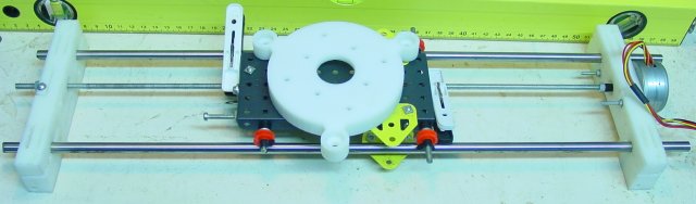
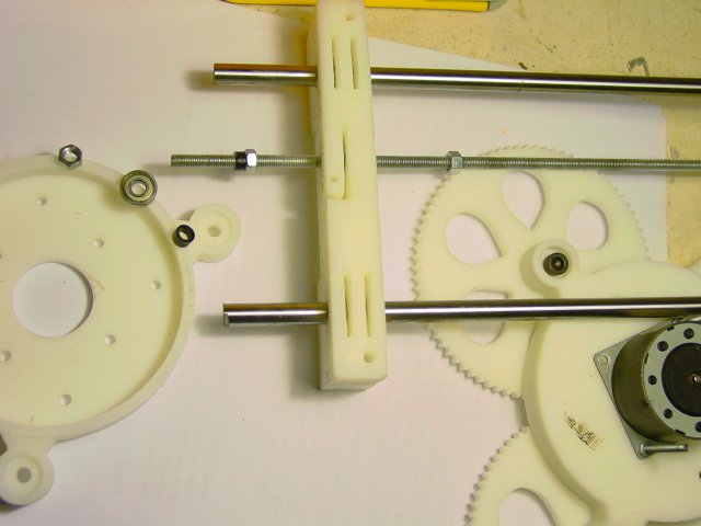
| 20:50, 16 December 2005 | Screw-drivenLinearAxis-linear axis with meccano carriage sml.jpg (file) |  |
28 KB | Assembled linear axis with Meccano carriage and spider for scale. | 1 |
| 01:44, 5 January 2006 | Half-roundWasherBearing-half-washer bearings installed.jpg (file) |  |
28 KB | Half-washer bearings installed in the extruder. | 1 |
| 01:43, 5 January 2006 | Half-roundWasherBearing-stacking half-washers.jpg (file) |  |
28 KB | Stacking half-washers in the bearing well | 1 |
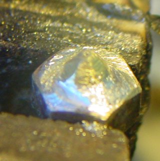
| 10:32, 16 July 2006 | InterchangeableNozzleMk2-crudel shaped nozzle.jpg (file) |  |
29 KB | Crudely shaped 0.5mm nozzle | 1 |
| 09:36, 16 July 2006 | InterchangeableNozzleMk2-M6 bolt centred.jpg (file) |  |
30 KB | M6 Bolt with a pilot hole in the centre | 1 |
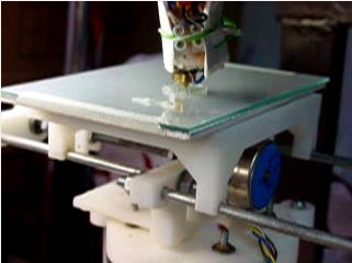
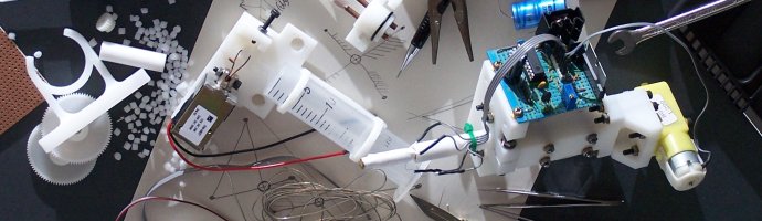
| 14:08, 11 May 2006 | VikOlliver-first run of x and y deposition sml.jpg (file) |  |
32 KB | The first run of the X-Y axes with extrusion and java-levelled Z axis. | 1 |
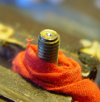
| 06:16, 4 June 2006 | BlogPhotosFromVik-polymorph feedstock jam sml.jpg (file) |  |
33 KB | Polymorph feedstock jamming up and wrapping around the threaded rod. | 1 |
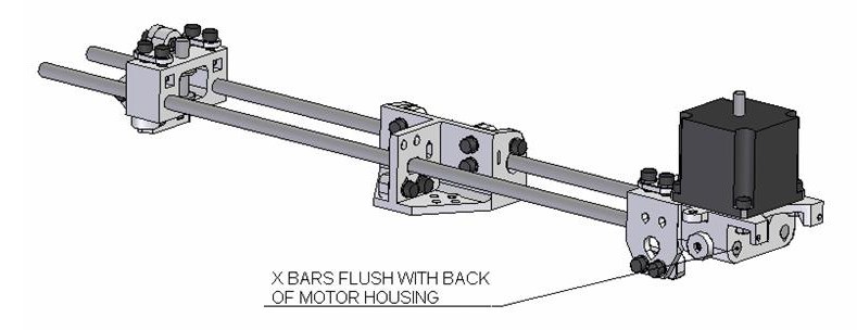
| 12:32, 17 October 2007 | AssemblingDarwinMachinery-17.JPG (file) |  |
35 KB | x axis complete | 1 |
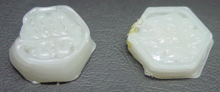
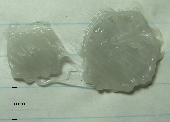
| 12:07, 27 June 2006 | BlogPhotosFromVik-cooled hex vs uncooled.jpg (file) |  |
36 KB | A cooled test hexagon (right) vs uncooled. | 1 |
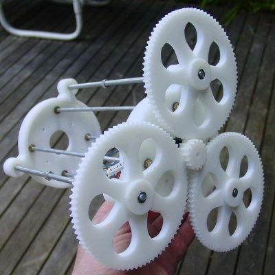
| 04:22, 18 December 2005 | VerticalPlatform-complete vertical axis gear end sml.jpg (file) |  |
38 KB | Vertical axis showing gear end | 1 |
| 00:04, 19 July 2006 | ShowCase-rr1 header.jpg (file) |  |
38 KB | Scaled version of header for quick loading. | 1 |
| 03:29, 11 March 2024 | URepRap logo.png (file) | 38 KB | RepRap logo with a micron in the middle | 1 | |
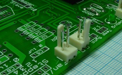
| 12:29, 4 June 2007 | UniversalControllerBoard 1 2-grtg V12 bodge.jpg (file) |  |
38 KB | How to bodge the TX Rx connectors on the V1.2 board | 1 |
| 12:54, 10 June 2006 | BlogPhotosFromVik-extrusion of hexagon 2nd layer closeup.jpg (file) |  |
39 KB | mov02395.mpg 2nd layer close-up of head | 1 |
| 14:03, 14 May 2006 | VikOlliver-first extruded recognisablesquare and hexagon sml.jpg (file) |  |
40 KB | This is the first recognisable extrusion by the RepRap. A square and hexagon. | 1 |
| 12:16, 23 May 2006 | Screw-drivenLinearStage-stage linkage 1 of.stl (file) | 40 KB | STL file for Stage/table linkage. Make 1. (Same model as linear axis) | 1 | |
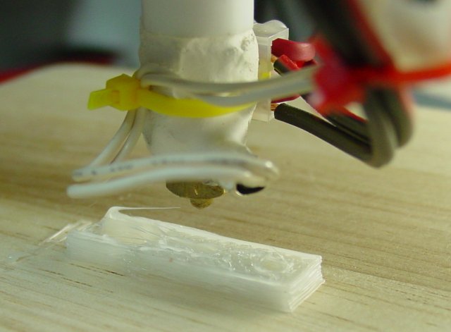
| 07:16, 5 July 2006 | BlogPhotosFromVik-deposition on 240 grit sml.jpg (file) |  |
40 KB | Deposition made at 95C on P240 sandpaper | 1 |
| 22:32, 17 August 2006 | BlogPhotosFromVik-first part freshly printed.jpg (file) |  |
41 KB | The first RepRap part, just cooled. | 1 |
| 20:34, 15 December 2005 | Screw-drivenLinearAxis-linear screw axis clamp collage.jpg (file) |  |
42 KB | Collage showing rail clamp, bearing and spider mechanism. | 1 |
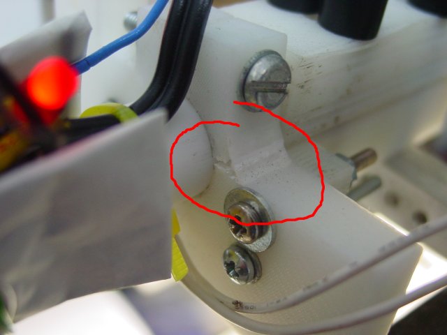
| 14:13, 22 June 2006 | BlogPhotosFromVik-break in mk2 extruder clamp sml.jpg (file) |  |
42 KB | 16mm clamp breakage on original Mk2 design | 1 |
| 13:42, 10 February 2006 | HighTemperatureMaterials-first concrete insulator.jpg (file) |  |
43 KB | The first concrete insulator just out of its mould. | 1 |
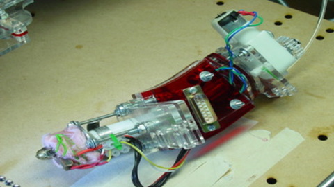
| 08:51, 31 January 2009 | PonokoExtruderAssembly-dsc04672.jpg (file) |  |
45 KB | The finished extruder. | 1 |
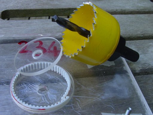
| 01:48, 18 February 2007 | HandmadeGears-mould and hole saw sml.jpg (file) |  |
45 KB | Small image of mould and hole saw | 1 |
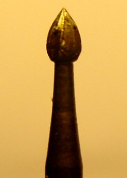
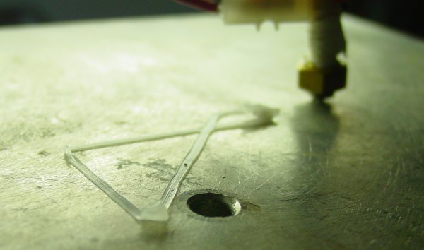
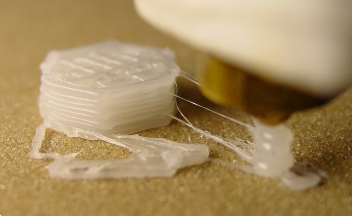
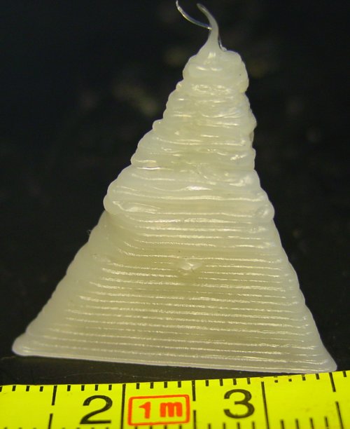
| 13:38, 20 July 2006 | BlogPhotosFromVik-first attempt at pyramid sml.jpg (file) |  |
47 KB | First attempt at depositing a flat-tipped pyramid | 1 |
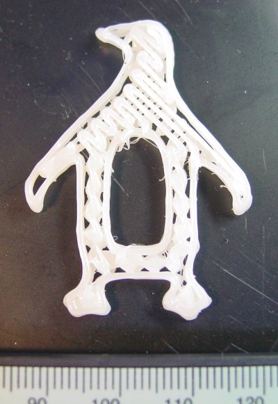
| 17:10, 17 November 2006 | BlogPhotosFromVik-filled penguin.jpg (file) |  |
48 KB | Filled-in penguin for LCA 2007 | 1 |
| 14:15, 8 June 2006 | RPOrders-drive-coupling.stl (file) | 48 KB | Mk 2 Extruder drive coupling | 1 | |
| 15:49, 16 June 2006 | BlogPhotosFromVik-defected test hex from above.jpg (file) |  |
49 KB | The test hex, made using Adrians code, shown from above. | 1 |