Search results
Create the page "Stripboard" on this wiki! See also the search results found.
Page title matches
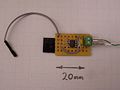
- |name = Stripboard Comms Controller |description = Stripboard Comms Controller12 KB (1,987 words) - 05:01, 25 July 2015
File:Stripboard-top.jpg (2,304 × 1,728 (1.35 MB)) - 10:38, 3 October 2009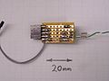
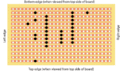
File:Stripboard-bottom.jpg (2,304 × 1,728 (646 KB)) - 10:39, 3 October 2009- = HOWTO: Building A Stripboard Stepper Controller (for a Unipolar Motor) = * A piece of stripboard with 2.54mm (0.1") spaced continuous track. It should be a minimum of 23 h7 KB (1,090 words) - 06:34, 29 November 2014
File:StepperDriverWithUDN2559-2559 Stepper Stripboard top.png Top view of 2559 Stepper Motor on Stripboard(516 × 606 (153 KB)) - 07:55, 17 March 2010- ...Rap controller boards. It is very simple to solder up on an old offcut of stripboard, or you can get a proper [http://parts.rrrf.org/product_info.php?products_i1 KB (230 words) - 20:05, 26 November 2011
- = HOWTO: Build A Stripboard Bipolar Slave Stepper Controller = * [[StripboardBipolarStepperController|HOWTO Build a Stripboard Bipolar Stepper Controller]]1 KB (158 words) - 05:08, 25 July 2015
- = HOWTO: Build A Stripboard Bipolar Stepper Controller = ...order repeatedly. The pinouts are 1 to 4 as seen from the top-down on the stripboard. Where you see 1->2 this means the voltage measured from pin 1 (negative p6 KB (906 words) - 05:09, 25 July 2015
- ...ication on plain perforated board. The design outlined here uses the same stripboard methods as suggested for other modules and is simpler to build. This image shows the rear of the stripboard so you can see the points that were separated.7 KB (1,092 words) - 05:11, 25 July 2015
- |description = Pololu Extruder Stripboard The idea is to make a dead simple stripboard mounted [[Pololu stepper driver board]] and connect it to the existing RepR3 KB (444 words) - 07:34, 10 January 2015
File:Pololu stripboard power.jpg (1,024 × 765 (179 KB)) - 16:39, 26 July 2010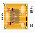
File:Pololu stripboard diagram.jpg (320 × 302 (39 KB)) - 21:40, 8 August 2010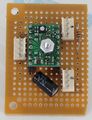
File:Pololu stripboard front.jpg (983 × 1,279 (308 KB)) - 23:45, 8 August 2010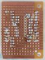
File:Pololu stripboard back.jpg (1,222 × 1,648 (549 KB)) - 23:45, 8 August 2010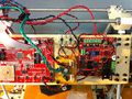
File:Pololu stripboard mounted.jpg (2,592 × 1,936 (1.49 MB)) - 23:47, 8 August 2010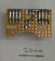
File:Mini-extruder-stripboard-back.jpg (908 × 1,008 (578 KB)) - 20:35, 13 April 2011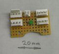
File:Mini-extruder-stripboard-front.jpg (1,072 × 988 (660 KB)) - 20:35, 13 April 2011
File:Mini-extruder-stripboard-cutting.jpg (2,440 × 1,068 (1.48 MB)) - 08:43, 9 March 2011


Page text matches
- ...hermoplastExtruder_2_0#Electronics|Electronics Section]] above. The small stripboard circuit you see here is identical to one channel of the standard PWM Driver38 KB (6,703 words) - 17:54, 13 October 2013
- |name = Stripboard Comms Controller |description = Stripboard Comms Controller12 KB (1,987 words) - 05:01, 25 July 2015
- #REDIRECT [[Building A Stripboard Comms Controller]]52 bytes (6 words) - 05:01, 25 July 2015
- ====Stripboard Designer 1.0==== ...ators.com/New%20Front%20Page/Documentation/Tools/Stripboard%20designer.htm Stripboard Designer 1.0]27 KB (4,082 words) - 12:06, 26 October 2021
- ...MAX6675.pdf MAX6675]] chip, and is easily put together on a small piece of stripboard that plugs into the I2C connector on the extruder controller board. [[Image:stripboard-top.jpg|400px]] [[Image:stripboard-bottom.jpg|400px]]5 KB (848 words) - 08:13, 27 November 2011
- ...holes. The end of the connector should be just flush with the edge of the stripboard.<br clear="all">[[Image:Usb-pcb-connections.jpg]][[Image:Usb-wire.jpg]] ...on the left view. Use a thin cable tie to attach the ribbon cable to the stripboard via the smaller holes. Leave a small loop free to give strain relief. Jum5 KB (921 words) - 21:28, 24 November 2023
- | stripboard||1||1||Electronics A neat way to make the electrical connections is to cut a piece of stripboard the same width as the top of the reprapped part of the extruder. Put two 411 KB (1,944 words) - 06:23, 18 March 2014
- ==Stripboard PCB as a heating Element==31 KB (5,100 words) - 21:49, 11 November 2018
- #REDIRECT [[Building A Stripboard Comms Controller]]52 bytes (6 words) - 05:02, 25 July 2015
- ...a solderless breadboard or an off-the-shelf prototyping board (perfboard, stripboard, etc), or11 KB (1,564 words) - 14:24, 15 January 2015
- ...that it is also quite straightforward to make it on a couple of pieces of stripboard. That is how I prototyped it, and that is described below as well. == Making the electronics using stripboard ==20 KB (3,299 words) - 23:41, 5 February 2024
- = HOWTO: Building a stripboard Extruder Controller = * A piece of stripboard with 2.54mm (0.1") spaced continuous track.8 KB (1,325 words) - 20:07, 26 November 2011
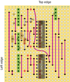
File:BuildingAStripboardExtruderController-ExtruderStripboardTop SN754410.png Extruder stripboard layout, component side.(800 × 1,135 (313 KB)) - 06:31, 17 March 2010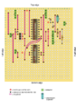
File:BuildingAStripboardExtruderController-ExtruderStripboardTop SN754410.svg Source for extruder stripboard layout(524 × 744 (495 KB)) - 06:31, 17 March 2010- = HOWTO: Building A Stripboard Stepper Controller (for a Unipolar Motor) = * A piece of stripboard with 2.54mm (0.1") spaced continuous track. It should be a minimum of 23 h7 KB (1,090 words) - 06:34, 29 November 2014
- #REDIRECT [[Building A Stripboard Stepper Controller]]54 bytes (6 words) - 22:57, 20 February 2014
File:BuildingAStripboardStepperController-StepperStripboardUnder.gif Underside of stripboard(535 × 316 (18 KB)) - 06:32, 17 March 2010- # Move motors and electronics (still on stripboard) onto the new RepRap frame. ...tely functional RepRap, though it is not a true RepRap because it has some stripboard controllers and so on. The final step is to produce a new RepRap using the1 KB (240 words) - 14:32, 6 December 2011
- ...the ZD1901 opto interrupter prevalent in the Southern Hemisphere, a simple stripboard assembly is required. Details [[DarwinZD1901Opto|here]].7 KB (1,036 words) - 15:24, 23 July 2015
- If all this checks out and you have verified the stripboard soldering, then you can apply power to the board. If you have a multimeter This is based on the older, [[BuildingAStripboardCommsController|stripboard comms controller]] designed by Simon.16 KB (2,457 words) - 09:39, 26 November 2011


