Search results
Create the page "Mks" on this wiki! See also the search results found.
Page title matches

File:MKS BASE PINS.pdf It is the PIN map for MKS BASE seris PCBA.(141 KB) - 04:03, 8 November 2014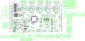
File:MKS GEN-PIN.PNG PIN map for MKS GEN series PCBA.(1,124 × 557 (56 KB)) - 04:09, 8 November 2014
File:MKS Base V1.0 source.zip MKS Base V1.0 Schematics(371 KB) - 09:15, 27 May 2014
File:MkS Base1.0.jpg MKS Base1.0 is base on the MEGA2560 and RAMPS1.4. It combine these two PCB toge(771 × 609 (636 KB)) - 08:17, 27 May 2014
File:MKS BASE V1.0.jpg MKS Base V1.0 is base on the MEGA2560 and RAMPS1.4. It combine these two PCB to(2,368 × 4,208 (1.64 MB)) - 08:27, 27 May 2014
File:MKS GEN.jpg (640 × 480 (145 KB)) - 21:11, 16 October 2014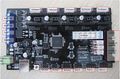
File:MKS GEN-1.jpg (843 × 557 (152 KB)) - 07:13, 17 October 2014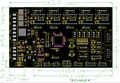
File:MKS GEN-A.jpg (845 × 587 (150 KB)) - 03:17, 22 November 2014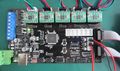
File:MKS GEN-B.jpg (750 × 443 (73 KB)) - 03:18, 22 November 2014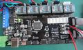
File:MKS GEN-C.jpg (750 × 457 (80 KB)) - 03:19, 22 November 2014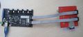
File:MKS GEN-D.jpg (750 × 340 (45 KB)) - 03:19, 22 November 2014
File:MKS GEN-F.jpg (409 × 218 (25 KB)) - 04:50, 22 November 2014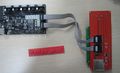
File:MKS GEN-J.jpg (750 × 459 (61 KB)) - 05:22, 22 November 2014
File:MKS GEN-G.jpg (749 × 446 (83 KB)) - 06:13, 22 November 2014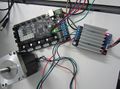
File:MKS GEN-H.jpg (750 × 559 (72 KB)) - 06:13, 22 November 2014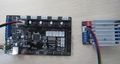
File:MKS GEN-I.jpg (750 × 400 (58 KB)) - 06:14, 22 November 2014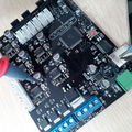
File:MKS-BASE2.jpg (750 × 750 (147 KB)) - 03:08, 24 November 2014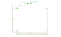
File:MKS Base-3.png (999 × 605 (17 KB)) - 03:09, 24 November 2014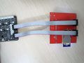
File:MKS Base-4.jpg (750 × 563 (70 KB)) - 03:10, 24 November 2014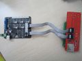
File:MKS base-5.JPG (1,000 × 750 (117 KB)) - 03:10, 24 November 2014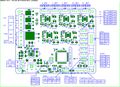
File:MKS-BASE-6.jpg (843 × 612 (152 KB)) - 03:11, 24 November 2014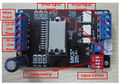
File:MKS TB6600 Connect.jpg (675 × 470 (433 KB)) - 03:27, 26 November 2014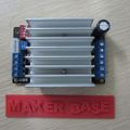
File:MKS TB6600.JPG (1,000 × 1,000 (135 KB)) - 03:28, 26 November 2014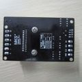
File:MKS TB6600-Back.JPG (1,000 × 1,000 (107 KB)) - 03:29, 26 November 2014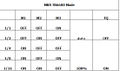
File:MKS TB6600 Mode.jpg (549 × 324 (80 KB)) - 03:29, 26 November 2014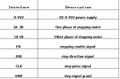
File:MKS TB6600 Desc.jpg (562 × 370 (116 KB)) - 03:30, 26 November 2014
File:MKS BT 1.jpg (282 × 432 (25 KB)) - 05:51, 26 November 2014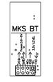
File:MKS BT2.jpg (372 × 578 (55 KB)) - 05:52, 26 November 2014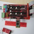
File:MKS BT3.JPG (1,000 × 1,000 (147 KB)) - 05:52, 26 November 2014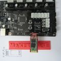
File:MKS BT4.JPG (1,000 × 1,000 (141 KB)) - 05:53, 26 November 2014
File:MKS BT5.JPG (1,000 × 1,000 (121 KB)) - 05:53, 26 November 2014
File:MKS-12864 OLED4.png (602 × 749 (81 KB)) - 05:08, 25 July 2015
File:MKS-12864 OLED1.jpg (500 × 500 (77 KB)) - 04:52, 25 July 2015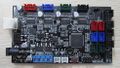
File:MKS-MINI.jpg (977 × 557 (128 KB)) - 02:19, 19 January 2015
File:MKS 2004LCD1.jpg (1,000 × 1,000 (153 KB)) - 03:39, 27 July 2015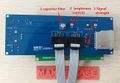
File:MKS 2004LCD2.jpg (650 × 451 (79 KB)) - 03:40, 27 July 2015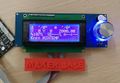
File:MKS 2004LCD3.jpg (650 × 447 (71 KB)) - 03:40, 27 July 2015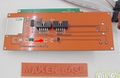
File:MKS 2004LCD4.jpg (382 × 249 (23 KB)) - 03:41, 27 July 2015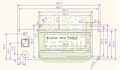
File:MKS 2004LCD5.jpg (857 × 499 (79 KB)) - 03:41, 27 July 2015
File:MKS CTR1.jpg (400 × 400 (35 KB)) - 04:49, 27 July 2015
File:MKS CTR 2.jpg (400 × 300 (36 KB)) - 04:50, 27 July 2015
File:MKS DRV88251.jpg (1,000 × 1,000 (102 KB)) - 02:22, 29 July 2015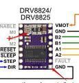
File:MKS DRV8825 2.jpg (252 × 264 (25 KB)) - 02:24, 29 July 2015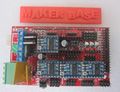
File:MKS DRV8825 3.jpg (750 × 575 (105 KB)) - 02:24, 29 July 2015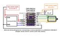
File:MKS DRV8825 5.jpg (655 × 407 (59 KB)) - 02:26, 29 July 2015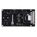
File:MKS MIN 12864 back (connector housings rotated).jpg Back view of a front load MKS MINI12864. EXP1 7 EXP2 housings are rotated 180 degrees.(600 × 600 (29 KB)) - 20:20, 23 June 2017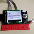
File:MKS MINI 12864.png (224 × 224 (72 KB)) - 20:23, 23 June 2017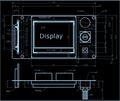
File:MKS MINI12864 dimensions front load.JPG (956 × 806 (108 KB)) - 20:26, 23 June 2017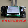
File:MKS Mini12864 front SD card slot.jpg (800 × 800 (131 KB)) - 20:27, 23 June 2017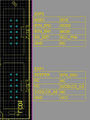
File:MKS MINI12864 LCD controller pin out - signal names.jpg (463 × 615 (43 KB)) - 20:27, 23 June 2017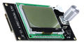
File:MKS MINI12864 side load cropped.jpg (418 × 210 (37 KB)) - 20:40, 23 June 2017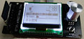
File:MKS Mini12864 front SD card slot cropped resized.jpg (444 × 210 (45 KB)) - 20:48, 23 June 2017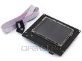
File:Mks tft28.jpg (800 × 600 (63 KB)) - 00:38, 15 November 2017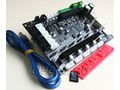
File:MKS SBASE V1.3.jpg MKS SBASE v1.3(800 × 600 (120 KB)) - 08:58, 18 October 2017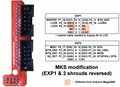
File:Re-ARM LCD adapter MKS Rev 4.jpg LCD adapter with EXP1 & EXP2 shields reversed (for MKS style displays)(2,825 × 2,038 (324 KB)) - 22:15, 14 March 2019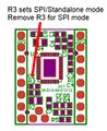
File:Mks-2130-SPI.jpg (297 × 364 (94 KB)) - 04:38, 15 February 2020


.jpg)


Page text matches
File:MKS BASE PINS.pdf It is the PIN map for MKS BASE seris PCBA.(141 KB) - 04:03, 8 November 2014File:MKS GEN-PIN.PNG PIN map for MKS GEN series PCBA.(1,124 × 557 (56 KB)) - 04:09, 8 November 2014File:MKS Base V1.0 source.zip MKS Base V1.0 Schematics(371 KB) - 09:15, 27 May 2014File:MkS Base1.0.jpg MKS Base1.0 is base on the MEGA2560 and RAMPS1.4. It combine these two PCB toge(771 × 609 (636 KB)) - 08:17, 27 May 2014File:MKS BASE V1.0.jpg MKS Base V1.0 is base on the MEGA2560 and RAMPS1.4. It combine these two PCB to(2,368 × 4,208 (1.64 MB)) - 08:27, 27 May 2014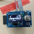
File:12864 OLED1.jpg {{MKS 12864OLED}} |image = MKS-MINI.jpg(1,000 × 1,000 (133 KB)) - 05:50, 25 July 2015
File:12864 OLED3.jpg MKS-12864OLED adopts OLED display and created by Makebase.(479 × 418 (137 KB)) - 03:46, 25 July 2015File:MKS MIN 12864 back (connector housings rotated).jpg Back view of a front load MKS MINI12864. EXP1 7 EXP2 housings are rotated 180 degrees.(600 × 600 (29 KB)) - 20:20, 23 June 2017File:MKS SBASE V1.3.jpg MKS SBASE v1.3(800 × 600 (120 KB)) - 08:58, 18 October 2017File:Re-ARM LCD adapter MKS Rev 4.jpg LCD adapter with EXP1 & EXP2 shields reversed (for MKS style displays)(2,825 × 2,038 (324 KB)) - 22:15, 14 March 2019

