SpoolHead
Release status: Experimental

| Description | Spool-printing toolhead
|
| License | |
| Author | |
| Contributors | |
| Based-on | |
| Categories | |
| CAD Models | |
| External Link |
Contents
Introduction
I am Jacob Bayless, and my team members are Mo Chen and Bing Dai. We are 4th year Engineering Physics undergraduate students at the University of British Columbia, and this is what we have chosen for our project course this year.
The spool-printing toolhead ("spoolhead") is a Reprap toolhead for printing with spooled, non-extrudable materials. The main goal is to print with copper wire, but steel and nichrome wire may also be printable. Possibly thread will be as well, although we are not planning to test this.
While we would love to be developing this toolhead for Mendel, these printed parts were not readily available when we began our project, and Darwin was deemed sufficient for our needs. Modifications to adapt the toolhead for Mendel should be minor.
Forum
http://dev.forums.reprap.org/list.php?143
Schedule
The project began in August 2009. The release date is expected to be early April 2010.
Motivation
While Reprap can print with a variety of plastics, efforts are currently being undertaken to extend this ability to the extrusion of low-melting-temperature alloys such as Field's metal. However, even with this in place, the Reprap's ability to print "active" (electronic or electromagnetic) components will remain limited, due to:
- The inability to print thin insulated wire, essential for tightly-wound coils;
- The high cost and low availability of Field's metal and similar compounds;
- The difficulty of printing fine tracks from liquid metal, due to surface tension;
- The operating range of printed components would be restricted to temperatures safely below 62 degrees C, the alloy's melting point.
The last point implies, for example, that the Reprap will not be able to use Field's metal conductors in an extruder for Field's metal, as it would melt itself during operation.
In his Ph.D thesis, Ed Sells discusses the mechanical design of the Darwin model. In the section "Remaining challenges for pure self-manufacture", he writes that, of the Reprap's own parts, the most difficult to self-manufacture would be "electronic components, motors, conductive cable, solenoids, and the heating element". He adds that "it is unlikely the machine will be able to self-manufacture these parts for at least a couple of years". The challenging element that all of these parts have in common is the printing of copper (or Nichrome) wire.
It is therefore clear that the ability to include wire elements in a printed part would greatly expand the Reprap's capability of self-manufacture, whilst allowing it to manufacture a wider variety of active components for other purposes as well.
Further applications may include:
- Printing steel wire reinforcements to strengthen a part in crucial areas;
- Printing flexible threads within parts to create durable "living hinges".
Software
To get started in the right direction, our image of what such a toolchain may look like is one that works in the Scalable Vector Graphics (SVG) file format. First, a 3D model (STL) would be sliced in the traditional way by software like skeinforge. Then, the slices would be exported to SVG, in individual layers representing the Z height. Users would then draw lines representing wires in the part layers freely as desired (and, possibly, vias to connect Z layers). The SVG model, now incorporating bulk plastic and wire information, would then need to be translated into G-code.
Due to time constraints, we are not planning to create special skeinforge-like software for digesting 3D models with wires incorporated in them. This may form a future project in its own right, or other members of the Reprap community may join in to create an accompanying software toolchain.
Of course, any software produced by our team for this toolhead (such as firmware, or modifications to G-code interpreters) will be released with the hardware plans.
The Spool-Printing Process
Unlike extrusion of a thermoplastic, spoolhead printing allows for use of materials that are impractical to melt; for example, metal wires. The flexible wires are laid as continuous strands within the printed part. Doing this requires the following automated processes: 1. Controllably feeding the wire from the spool; 2. Bonding the wire to the printed part; 3. Cutting the wire at the desired location;
This process is sufficient to handle an arbitrary number of wires on arbitrary horizontal planar paths, allowing the printing of many desirable features, such as PCBs, routing. Further software developments may also open the possibility of printing a subset of 3-dimensional embedded wire figures, such as helical coils. Printing of arbitrarily complex 3D wire shapes, such as knots, would probably be impossible with the proposed methods; however, the vast majority of useful devices do not require this level of complexity.
Controllably feeding the wire from the spool
Three methods have been proposed for this. The first is a stepper-actuated pinchwheel extruder, or similar device (such as a stepper motor capstan feeder), functioning in a similar way to the thermoplastic extruder. This method should work reliably, and has the advantage of being able to accommodate a wide range of wire diameters. More importantly, it has a high level of compatibility with existing electronics and software, due to its similarity to the thermoplastic extruder. However, wires must be relatively stiff (such as copper). The stepper does not have a high torque/narrow shaft requirement like the thermoplastic extruder motor, because there is very little resistance to the wire's motion. A good grip is, however, important.
Due to the convenience of compatibility, and the ability to handle fine wire diameters, this was the favored method for the SpoolHead. However, experiments found that the current electronics cannot apparently drive two independent stepper motors; thus, a redesign was performed to use the second method instead.
The second method uses a solenoid-actuated mechanical pushbutton-advance pencil to act as a sort of linear stepper. This has the advantage of being extremely cheap, as solenoids and mechanical pencils are very common. Also, solenoids are more likely to be printable in the future than stepper motors. For reverse feeding, two pencils could be used back-to-back. The main disadvantage of this method is that a given pencil can accommodate only a certain diameter of wire (eg. 0.5 mm, a fairly thick gauge). The spoolhead's first printed material is planned to be 0.3mm copper wire; however, 0.3mm pencils are (to my knowledge) hard to find outside of Japan.
The mechanical pencil method is therefore the current plan. Concept drawings have been uploaded to the gallery.
Update (26 March): Mechanical pencil method successfully tested; using servo actuation for now. Video
The third proposed method is to integrate the SpoolHead into a thermoplastic extruder (presumably with a wider nozzle diameter than existing variations). The wire would be drawn in by the molten plastic's viscous flow, and extruded together with the plastic. If it worked, this would guarantee a strong bond between the wire and the printed part. However, it suffers a significant drawback in being unable to extrude wires without simultaneously extruding plastic; this might be acceptable for some applications but not all. Furthermore, the method has many associated uncertainties; for example, would the wires jam easily? As a result, given tight deadlines for this project, it is considered too risky to pursue at the moment.
Bonding the wire to the printed part
There are three proposed methods for this as well: Using superglue, using UV-curing resin, or using heat.
A small coating of superglue could be applied to the wire just as it exits the spoolhead, forming an instant and tenacious bond to the printed part. The attraction of this method is that a superglue coating is all but guaranteed to successfully form a bond. There are, however, difficulties: It would be difficult to design a superglue-based extruder that does not require heavy maintenance to avoid fouling; superglue is expensive in large volumes; and if an error should cause too much superglue to be applied, the results could be very messy.
The third method would replace superglue with a UV-curing epoxy. This maintains all of the favourable properties of superglue, but without the risk of fouling the extruder itself, as the epoxy will not cure on its own. However, the drawbacks are the cost and complexity associated with a UV epoxy system.
The thermal method would involve heating both the wire and the local surface of the printed part where the wire is to be bonded. The main advantages of this method is cost: heat is very cheap and renewable. It also results in a mechanically and electrically simple design, as any actuators required for dispensing adhesives are replaced with a heating element. Finally, it would result in a strong printed part, as there would be no contamination introduced by superglue or resin between the plastic layers. The challenge of this method is its uncertainty: Can the surface of the plastic be heated to a high enough temperature in a reasonable period of time to form a bond with wire? No experiments have been conducted to confirm this. Given the drawbacks of the adhesive methods, determining the feasibility of the thermal bonding method is very important; as a result, this method is the one we will pursue.
BeagleFury has proposed an alternate, mechanical method; see the discussion page.
Cutting the wire at the desired location
Wire-cutting is to be carried out mechanically. The original proposal was to use fingernail clippers to cut the wire, but this has been determined to require too much space in the extruder. It's important to have the cutting device as close as possible to the point of contact with the printed part, because the distance between these points determines the minimum length of wire that the system will be capable of printing.
A new solution has been proposed by UBC Engineering Physics' Bernhard Zender. The idea is to rotate a cutter inside a cross-drilled hole in the main screw. Illustrations of this method are posted in the gallery.
Alternative wire cutting methods:
1. Swing-cutter illustrated in the gallery.
2. Alternatively: A "cigar cutter" driven by conical wedge/cams which are fed by internal threads would have excellent mechanical advantage for its cutting force as well as being slim.
eg: \|/ /()/ /|\
key: /( =blade
/|\=cone with internal threads
Photos and Drawings
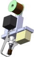
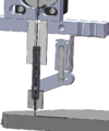
Design progress, 02 Feb 2010
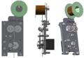
OLD wire-cutting method proposal
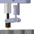
NEW wire-cutting method proposal
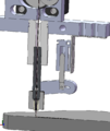
Cutaway view of wire cutter
Cutaway view of wire cutter
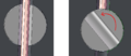
Close-up of cutting mechanism
Sheet metal NEMA wire feeder design
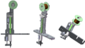
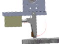
NEW Pencil fed design
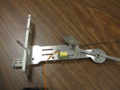
Parts freshly cut on waterjet


Working Notes
Current BOM (subject to change):
- Mechanical Pencil (0.3mm if possible, 0.5mm otherwise)
- Two solenoids
- Nichrome heating element
- Thermistor/Thermocouple
- Insulating materials
- PEEK/PTFE insulator (just like on Darwin/Mendel)
- Drilled M6 stainless steel studding (preferable over brass)
- 3x type 688 skate bearings (OD 16mm - smaller than standard)
- Printed parts/Sheet metal parts
- Cross-drilled hard metal (not stainless) 3mm rod
- Compression Springs
- Screws and nuts
- 1x Arduino Extruder Controller (same as on standard extruder)
Files
Tooling
Description of the tooling requirements
Process
What is making the part like?
Entrepreneurship (Kits)
No plans exist to produce kits for this toolhead.