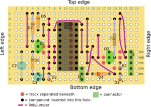
Stripboard JDM PIC Programmer
Contents
JDM PIC Programmer
Note: This is a preliminary design and has not yet been tested
Introduction
This is based on the original JDM programmer design. The original design requires either a PCB or fiddly fabrication on plain perforated board. The design outlined here uses the same stripboard methods as suggested for other modules and is simpler to build.
This programmer is only required for bootstrapping a machine (see RepStrap), as the complete machine will include it's own PIC Programmer.
Requirements
Schematic
Preparing the board
Making the board
Board connections
- J1 - Serial connector
- TxD
- GND
- CTS
- DTR
- RTS
- J2 - Mode selection
- Common
- For old PICs
- For new PICs including 16F628 (for RepRap projects)
If you're planning of programming a variety of PICs, you should connect J2 to a switch so you can easily switch configurations. If you're only planning on programming PICs for the RepRap project, you can just hardwire pin 1 to pin 3 with a jumper (and leave pin 2 disconnected).
Usually you will be connecting a cable from the programmer to a 9-pin serial connector for plugging into a PC. Use a female 9-pin connector. Wire J1 as follows
- TxD to pin 3 (on the 9 pin connector).
- GND to pin 5
- CTS to pin 8
- DTR to pin 4
- RTS to pin 7
Variations
Troubleshooting
See Also
- RepStrap
-- Main.SimonMcAuliffe - 11 Mar 2006
