TMC2130
Collection of information about TMC2130 stepper driver boards.
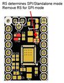
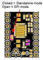
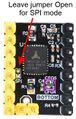
And in particular; how to use solder jumpers on the driver board to switch between Standalone mode and SPI mode on TMC2130 driver boards
On-chip 5V regulator
Please note that there is an internal 5V linear regulator, on the chip itself, and the about 20mA that the logic on the chip uses, will cause the following heat dissipation at different stepper supply voltages[1].
- 0.1W @ VM=12V
- 0.3W @ VM=24V
- 0.6W @ VM=36V
- 0.8W @ VM=45V
So a heat sink, that can help remove this heat from the board/chip, should always be used.
Good Heat Sink sizes. The bigger the better:
Hardware
Watterot
Design files: https://github.com/watterott/SilentStepStick
Versions: V1.0, V1.1, V2.0
Pictures:

Pinout details:
Fysetec
Design files: https://wiki.fysetc.com/TMC2130
Versions: V1.0, V1.1, V1.2
Pictures:
Pinout details:
makerbase
Design files: https://github.com/makerbase-mks/MKS-TMC2130
Versions: V1.0
Pictures:

(R3 is typically a 0 ohm jumper chip)
Pinout details:
BTT
Design files:
Pictures:
V1.1
V2.0
V3.0


Pinout details: