Template:RepRapPro printing
Settings
RepRapPro 3D printers are being sold as a complete printing solution, as such the RepRapPro host software comes with pre-tuned print settings for PLA and ABS filament. We encourage people to play with and put forward improvements to the print settings, but would advise starting with the provided print profiles and working from there.
Warming up
The provided print profiles include a startup routine which will prepare the printer before the print starts. This routine does not include a command to wait for the heatbed to reach the desired temperature, (this is because the heating of the bed can take up to 20mins for ABS printing, and it would be quite disconcerting for the printer to sit there for ages apparently not doing anything and for it to suddenly start after all this time).
So before starting a print, you will need to heat the bed to a suitable temperature for printing:
Huxley: 95C for PLA and 140C for ABS, (bed temperatures are not calibrated on the top surface of the bed, so these values may appear rather high to some people).
Mendel: 55C for PLA and 110C for ABS.
Preparing a file to print
Your 3D model will need to be processed into a format which the printer understands. This is known as a GCode file (print commands are GCodes, see this reference).
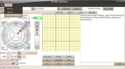
Before you can process a 3D model, you may need to tell Pronterface where to find the slicing tool. Click on Settings | Options and check that slicecommand and sliceoptscommand point to the location of your slicing tool. These will normally be:
python ./skeinforge/skeinforge_application/skeinforge_utilities/skeinforge_craft.py $s
python ./skeinforge/skeinforge_application/skeinforge.py
respectively. The pronterface software includes a customised copy of skeinforge in the subdirectory called ./skeinforge .
The 3D model will need to be in the STL file format. The software will load either a pre-processed GCode file or an STL 3D model. Click on Load file and select an STL file to process it. You will see progress of this process in the log window.
Once complete, the log will indicate how much filament will be used to print the model. You can then either print direct form USB or copy the file to the MicroSD card in the machine.
If printing from USB, your .gcode file will have been automatically loaded.
It is recommended, however, to print from the MicroSD for a number of reasons. When printing from USB, the print can be adversely affected by the host PC giving the printer a low priority over other running applications, slowing down the stream of commands. Also, the USB connection appears to be quite sensitive to AC noise on the power cable to the host PC.
To print from the SD card, copy the file to the card (which can be done through the printer interface with the SD card still in the machine, but it is much quicker to insert the card into the host PC and copy the file. Just make sure you INIT SD once the card is re-inserted).
Starting a print
To begin a print, you need to select the file you wish to print. Either from the Load file button to print direct from USB, or from the SD Print button.
Once the print starts, the machine will go through the following startup routine:
1. The printer moves all 3 motion axes in a negative direction to find X, Y, and Z zero.
2. The nozzle is heated to the relevant extrusion temperature.
3. Once extrusion temperature has been reached, the machine will print an outline before printing the component(s) to ensure the melt chamber behind the nozzle is primed.
When not required to move, the Z motors are de-activated. This can be a useful feature as it allows the Z height to be tweaked and the X axis to be levelled whilst the outline is being printed. Simply rotate the Z couplings by hand to get a good first layer (filament slightly squished). If you have moved the two couplings in unison to adjust the Z height, you will need to adjust the Z offset in the firmware before the next print, otherwise you will end up having to tweak the Z height manually at the start of each print.
To adjust the Z height in firmware, use the command M206 Z<value> where <value> is the amount in millimeters by which you wish to adjust the Z height. If the first layer is too close to the bed, you need to effectively move the bed down, so <value> will be negative. If the nozzle is too far from the bed during the first layer, <value> should be positive to raise the bed. The maximum adjustment is +/-1.27mm. Note that the Z height adjustment is stored in non-volatile memory on the printer so your printer will remember this setting even if you remove power.
Depending on the distance of the limit switches to the bed it may be necessary to offset the printhead. Check if the nozzle of the printhead is over the bed if you use the command G1 Y0 and G1 Y135 (Huxley) or G1 Y195 (Mendel). If this is not the case large prints will fail because they will be not on the bed. Set an offset by using the command M206 Y<value>. Sample: With M206 Y-8 you offset the Y axis by -8 mm. Check also X axis. Of course, you can always move the limit switch.
