Whot End
Release status: Experimental

| Description | New hot end design with more flexible mount system
|
| License | |
| Author | |
| Contributors | |
| Based-on | |
| Categories | |
| CAD Models | |
| External Link |
Contents
Introduction
I'm proposing a new hot end design with a more flexible mount system. It can be lightweight and still mechanically very 'stiff'
Concept
The main design feature is a cylinder in which the heater and insulation are mounted.
The heater will be clamped in the centre of a cylinder using 3 screw that are running through threaded holes in the cylinder. The screws have pointed tips to increase grip and decrease heat transfer, the heater body has shallow pits where the screws touch to increase grip.
I've made a quick sketch up model to illustrate this. This sketch up drawing doesn't include the barrel yet.
The advantages of this design are:
- Easy adaptation to existing extruder-hotend mounting systems:
- A 16 mm rod could be clamped the same way as the copper head is clamped to allow legacy mounting to wade's extruder.
- cylinder can easily be fixed into an MDF disk, to allow easy use with an arcol.hu v3 style mounting system.
- Fix |_ profiles to the cylinder (inside or outside) using screws and threaded holes in the cylinder or pop rivets.
- Attach metal 6 sided rods directly using screws and threaded holes in the cylinder.
- The cylinder could be extended all the way up to the extruder and can be incorporated in the extruder design. Holes can be drilled/strips can be cut out to manipulate airflow, cooling and weight.
- Flexible mounting system to exchange hot ends:
- The heater& insulation can be easily exchanged by loosening the 3 screws while the cylinder can stay attached to the extruder.
- A wide variety of existing hot end designs can be easily adapted to fit into cylinder mount.
- Improved mechanical and thermodynamic properties:
- This type of hot end mount can be fairly lightweight and mechanically 'stiff'.
- This mount system takes away most mechanical stress from the barrel of the hot end. Because of this it is possible to redesign the barrel to improve on its thermodynamic properties.
proof of concept - prototype
Cylinder Mount
I made a first prototype to experiment with this design.
For this I am using an aluminum cylinder, as it is lightweight, a good thermal conductor and easy to work with.
I'm using a cut to measure piece of aluminum tube. OD: 32 mm ID: 26 mm length: 26 mm
The cylinder has 3 M3 threaded holes, evenly spaces around the centre.
Heater

I do not have easy access to proper tools, so i need to do everything with hand tools and a powerdrill. I found a nice copper hose connector and a welding post copper nozzle in the local DIY market. The hose connector has a 3 mm inner diameter The nozzle has a 6mm outer and a 0.8 mm inner diameter that seems to runs through the whole length of it.
I drilled a 5.5mm hole in the top of the hose connector, made the welding nozzle (6mm) slightly conical and hammered it in.
(hopefully it wont fall out during heat up..). because of the hammering the nozzle got a bit smaller. I opened it up with a 0.6 mm pin.
I opened up the inside of the nozzle bit by drilling into the hose connector from the back with a 3mm drill. Nozzle channel length should be 2 mm now.
The hose connector bit that goes into the hose got cut to about 8 mm and filed down to 6mm OD.
I will use insulated nichrome wire and fire cement for the heater. I will insulate the cement with tape and heat resistant silicone. It should not touch the cylinder.
The heater has small pits drilled into it where the clamp screws touch.
The nichrome wire and thermistor are still underway.. so I'm stuck here for now.
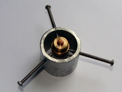
Front view of the prototype

Back view of the prototype


Barrel
The barrel could be mounted either directly to the hot end with the standard methods or/and it could be pressed against the heater using crews that are threaded into the cylinder at an angle. This could allow for different materials to be used into a barrel (fire silicone?)
Im will be building a hot end to print PLA. Haven't looked into the other popular plastics very much. PLA's thermal properties Glass transition temperature: 60-65 C Melting point 173-178 C Strangely enough I couldn't find anything about the thermal conductivity of PLA. Im guessing from other polymers that it should be below 0.50 W/m.K (Does anyone know? It would be very valuable to me to know how its conductivity is compared to PTFE's )
PTFE : 0.23 W/m.K http://webphysics.davidson.edu/faculty/dmb/PY430/Friction/teflon.html
My question regarding barrel design is the following:
from what temperature does PLA require to be guided by a barrel? I would assume from its glass transition phase.
When the system is not printing, the length of PLA that goes into glass transition or melts is a function of heater temperature heat transfer from heater to barrel by contact. (which is function of the contact surface& pressure) heat transfer within the barrel (which is function of the barrel OD diameter) heat transfer within the filament heat transfer from barrel surface to the air (function of surface area) room temperature& speed of airflow
If the filament can be cooled more efficiently, the barrel length could be shortened, as less of the filament will be hot enough to get into the glass transition zone. If the barrel is shorter, the filament could be cooled directly by airflow.
It would be far more efficient blow air directly onto the PLA filament to cool int instead of cooling the PTFE barrel in which the filament sits.
So maybe the barrel length could be made shorter than the length that is currently used?
Also a thinner barrel would result in less heat transfer from the barrel to the filament and better barrel/filament cooling. If mechanical stress on the barrel could be reduced, how much thinner can it be?
Has anyone attempted yet to model this? How would this best be modeled? Any thermodynamics engineers in the house? :)
The cylinder mount design should be really well suited to experiment with different barrels designs.
If you decide to give it a go, please share your thoughts and results on this page. If you have can answer some of these questions, you've run simulations, or got some hints on simulation for me, please share! Thanks.